Commax JNS-4CM User Manual Download Page 7

7

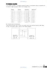
This system is designed for micro process based Data communication, hence setting up identification
numbers is required to activate communication function.  

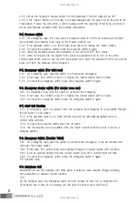
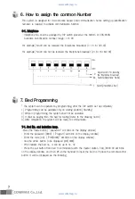
66--11.. IInntteerrpphhoonnee 
- Interphone No. shall be assinged by DIP switch placed at the bottom of CDS-90AN. 

Available identification number range: 10~99

For example) No.43 can be received the interphone broadcast (1+2+8+32=43) 

For example) No.43 can not be received the interphone broadcast (2+8+16+64=90) 

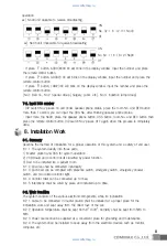
6. How to assign the common Number

* The system can be operated by programming, after the DIP switch set up completely. 
1) Programming can be available only on waiting position (Standby). 
2) While in programming, the system shall not be operated. 
3) It shall be paging from the bed for testing.(Refer to the drawing no.9-4) 
4) After completion, the system will be ready to communicate. 
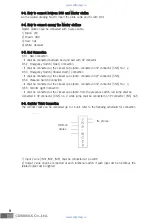
77--11.. B

Beedd N

Noo.. a

anndd IInndduuccttiioonn lla

am

mpp..

-Press the mode button.(

“ password " will blink on the display window) 

- Enter the password (9999). (

“Program" will blink on the display window) 

- Enter the code (00). (

“Pr00[0000]" will blink on the display window) 

- Use the arrow button to be displayed pr01[0000] 
- Pr02 indicate the bed no., it can be up to no. 32. 
- Press the call button from bed to communicate with the master station, CALL>XXXX-XX will blink 
on the display window, and then lift up the handset to input the bed no. If press the remote-control 
button, it will be displayed as the following. 

7. Bed Programming 

1- Switch(Interphone No.1)

64- Switch(Interphone No.64)

Reject switch for receiving
the Interphone broadcast

P-

www.safemag.ru

www.safemag.ru

Summary of Contents for JNS-4CM

Page 1: ...n particular precautions for safety before using a product and follow instructions to use a product exactly The company is not responsible for any safety accidents caused by abnormal operation of the...

Page 2: ...System Specification 3 System Feature 4 Signals Lamp Specification 5 Functions Operation 6 How to assign the common number 7 Bed Programming 8 Installation 9 NURSE CALL System Drawing 3 3 3 4 4 7 7 8...

Page 3: ...em m D Di im me en ns si io on n Master Station 240 L x 220 W x 90 H DDS 240 L x 129 W x 70 H 2 2 3 3 P Po ow we er r R Re eq qu ui ir re em me en nt t Power Source 220V Input Frequency 57Hz 63Hz Powe...

Page 4: ...turn on and Call xxxx Bed No will be displayed 5 5 2 2 S Su ub b S St ta at ti io on n F Fu un nc ct ti io on n 5 2 1 Communication with master and sub station Press the call button in sub station to...

Page 5: ...or r s sh ho ow we er r r ro oo om m u us se e 5 6 1 For emergency case push the switch to announce the emergency 5 6 2 If that case the corridor Lamp is on Display the master station with red lamp 5...

Page 6: ...one Lift up the handset press the Interphone button and DIAL button 00 All master stations and Interphones receive the broadcasting The master station on the phone with BED can not receive the broadca...

Page 7: ...erated 3 It shall be paging from the bed for testing Refer to the drawing no 9 4 4 After completion the system will be ready to communicate 7 7 1 1 B Be ed d N No o a an nd d I In nd du uc ct ti io on...

Page 8: ...Master station and DSS for system operation 2 PCB Board and Control Circuit classified by power function 3 Bed to be installed ion a patient room 8 1 2 All wires shall be connected individually 8 1 3...

Page 9: ...8 5 3 Emergency Switch Shower Room Connection It shall be connected at the closest sub station connected in 2P connector CN8 8 5 4 Presence Switch Connection It shall be connected at the closest sub s...

Page 10: ...able by parallel Refer to the drawing no 9 4 8 8 Transfer phone call Connection Total bed that receiver bed to convert and receiver bed to be converted should be within 48ea The way of connection shal...

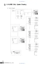
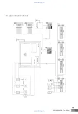
Page 11: ...9 1 System Diagram 9 NURSE CALL System Drawing 11 www safemag ru www safemag ru...

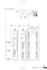
Page 12: ...9 2 System Wiring Diagram 12 www safemag ru www safemag ru...

Page 13: ...13 9 3 Parts Name and Connecting Method 9 3 3 How to connect between JNS 4CM and DSS www safemag ru www safemag ru...

Page 14: ...9 4 System Connection Schematic 14 www safemag ru www safemag ru...

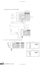
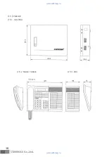
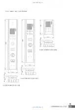
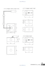
Page 15: ...9 5 Dimension 9 5 1 JNS PSM 9 5 2 Master Station 9 5 3 DSS 15 www safemag ru www safemag ru...

Page 16: ...16 9 5 6 NURSE CALL SUB STATION FLUSH MOUNTED JNS 102 FLUSH MOUNTED JNS 1000 FLUSH MOUNTED JNS 2000 www safemag ru www safemag ru...

Page 17: ...17 www safemag ru www safemag ru...

Page 18: ...18 9 5 7 Emergency Switch Toilet 9 5 8 Presence Switch 9 5 9 Emergency Switch Shower room www safemag ru www safemag ru...

Page 19: ...19 9 5 10 Emergency Switch Toilet Pulling style 9 5 11 Corridor Light 9 5 12 Interphone www safemag ru www safemag ru...

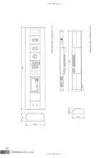
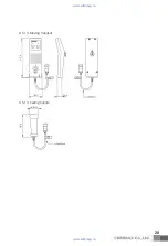
Page 20: ...9 5 13 Moving Handset 9 5 14 Calling handle 20 www safemag ru www safemag ru...

Page 21: ...21 Memo www safemag ru www safemag ru...

Page 22: ...3 11 Sangdaewon dong Jungwon gu Seongnam si Gyeonggi do Korea Int l Business Dept Tel 82 31 7393 540 550 Fax 82 31 745 2133 Web site www commax com Printed In Korea 2009 11 www safemag ru www safemag...

Reviews: