5
3. Parts Names
1
2
8
3
4
5
6
7
① HANDSET
⑤ INTERPHONE BUTTON
② TFT-LCD
⑥ DOOR OPEN BUTTON
③ POWER LED
④ MONITORING BUTTON
1. Red: Talk (Audio)
2. Blue: GND
3. Yellow: Power (+12V)
4. White: Video
▷
Polarity of the camera connector
1. Red: Talk (Audio)
2. Blue: GND
3. Yellow: Power (+14V)
4. White: Call signal
▷
Polarity of interphone connector
5. Wiring and Connection Instructions
⑦ MENU BUTTON
User Manual
(1EA)
Connector
(1EA)
Wall bracket mounting
screw
(4EA)
Monitor fixing
screw
(1EA)
Wall bracket
for monitor
(1EA)
4
4. Package Contents
⑧ POWER SWITCH
4
5
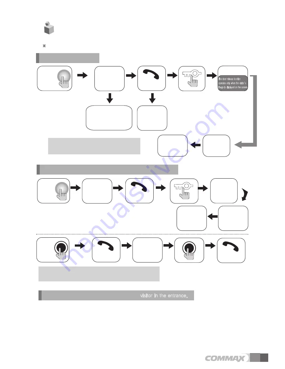
The visitor
presses the
call button on
the camera
A chime
sounds
The visitor
’
s
image appears
on the monitor
Hang-up the
handset
Ends the call
A view of the front door can be seen anytime the
entrance button is pressed and a dialog can be made
with anyone at the front door.
Dialog duration
60
seconds at
a time
Open the door
The door release function
operates only when the visitor’s
image is displayed on the screen
Dialog begins
1. Calling of visitor
6. Operation
�
Caution : Do not hold the handset at your ear when you press hook switch to switch call.
The display will be shown up
for 60 seconds and turned off
automatically
Dialog between the interphone and camera is possible only when the
visitor
’
s image is visible on the monitor screen.
A three-way
conversation can take
place if the monitor or
interphone is
picked up
simultaneously
"Tu-Tu-Tu"
Sound
A chime rings
simultaneously
from both the
monitor and
interphone
Hang-up the
handset
Open the door
End the dialog
Call to the
monitor
Dialog begins
Dialog begins
Dialog begins
A visitor
calls from
the entrance
Call
from the
monitor
2. Communication with the optional Interphone
3. Monitoring
: function to see the image of
visitor in the entrance
.
(On stand-by mode - status of putting handset down ) Operation
- By pressing the Monitor button repeatedly, the monitor will work as following in order.
Camera 1
Camera 2
OFF
Camera 1
......
(One talking mode - status of putting handset up) Operation
- By pressing the Monitor button repeatedly, the monitor will work as following in order.
Camera 1
Camera 2
Camera 1
Camera 2
......


