V30/30 DISTRIBUTION PANEL
SETUP AND OPERATION MANUAL
OPERATION - PAGE 13
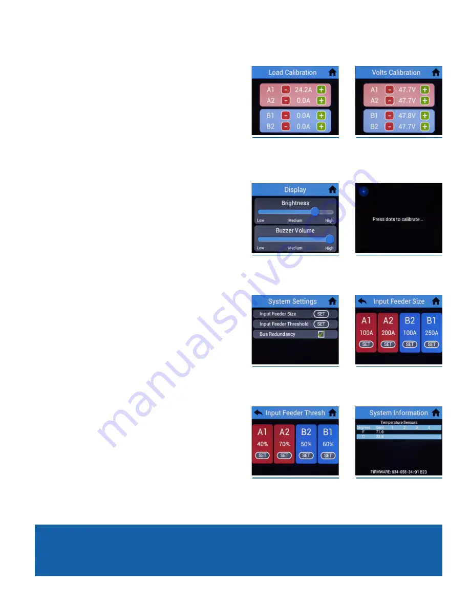
5.4 bus Calibration
To access bus calibration settings from the home screen, press the
Settings icon, then press Bus Calibration.
5.4.1 bus Load
Bus Load can be adjusted up to +/- 15 increments
(+/- 15A)
. Voltage
adjustment offset is shows on the right side of the display.
5.4.2 bus Voltage
Voltage can be adjusted up to +/- 30 increments
(+/- 3.0V)
. Voltage
adjustment offset is shown on the right side of the display.
5.5 System
To access system settings from the home screen, press the Settings icon,
then press System.
5.5.1 Display
5.5.1.1 brightness/buzzer Volume
The display brightness and buzzer volume can be adjusted by moving
the sliders.
5.5.2 Touch Calibration
This setting prompts user for permission to proceed with touch
calibration. Follow instructions on screen to continue.
5.5.3 Settings
5.5.3.1 Input Feeder Size
Press the SET button to adjust feeder fuse size for A1, A2, B2, and B1
busses.
1. Use keypad to enter a feeder fuse size between 100A and 300A.
2. Press SAVE button to save feeder fuse size, or CANCEL to revert back
to old feeder fuse size.
5.5.3.2 Input Feeder Threshold
Press the SET button to adjust feeder fuse threshold for A1, A2, B2, and
B1 busses.
1. Use keypad to enter a feeder fuse threshold between 40% and 100%.
2. Press SAVE button to save feeder fuse threshold, or CANCEL to revert
back to old feeder fuse threshold.
5.5.3.3 bus Redundancy
Turn bus redundancy ON/OFF by pressing the check box next to Bus
Redundancy.
5.5.4 Information
This screen displays system information about controller and
temperature sensors.
Cont = Controller internal temperature sensor. 1-4 are reserved for
optional external temperature sensors.
Figure 17. bus Load Calibration
Figure 18. bus Voltage
Calibration
Figure 19. Display
Figure 20. Touch Calibration
Figure 21. Settings
Figure 22. Input Feeder Size
Figure 23. Input Feeder Threshold
Figure 24. System Information


