6
106197
DECORATIVE PATIO FIRE
PROPANE/LP GAS
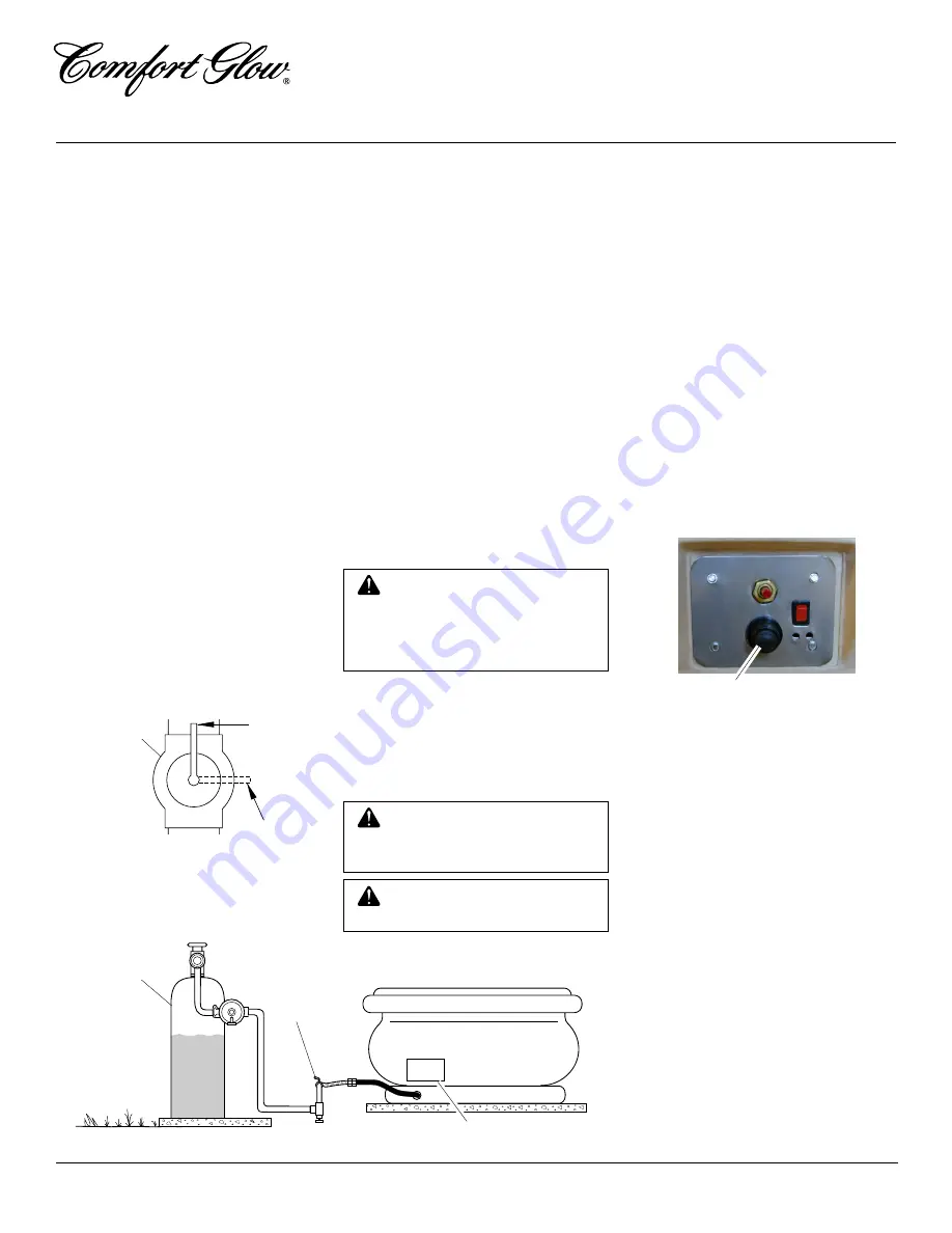
Figure 5 - Equipment Shutoff Valve
ON
POSITION
OFF
POSITION
Open
Equipment
Shutoff Valve
Figure 6 - Checking Gas Joints
Propane/LP
Supply Tank
Equipment
Shutoff
Valve
Control Valve Location
SETUP
Your Comfort Glow Patio Fire is designed
to operate with lava rock piled in and around
the burner, and refractory logs placed on top
of the lava rock.
Carefully pour supplied lava rock into basin
to cover the burner. Be sure that the burner
and burner ports are covered completely by
lava rock to better disperse the flame and to
create a more natural looking fire.
Place the six refractory logs on top of the
lava rock. The arrangement is left to your
personal preference. Try different place-
ments to achieve your desired flame pattern.
Note:
Sooting on the logs is natural. You
may clean with a soft bristle brush.
CAUTION: Place lava rock
carefully. Be careful not to dam-
age the burner, ignitor electrode,
or thermocouple when adding the
lava rock.
WARNING: Allow logs and
lava rock to cool completely be-
fore handling or rearranging logs.
INSTALLATION
Continued
Closed
4.
Check all joints of gas supply piping
system. Apply mixture of liquid soap
and water to gas joints. Bubbles form-
ing show a leak.
5.
Correct all leaks at once.
6.
Reconnect unit and equipment shutoff
valve to gas supply. Check reconnected
fittings for leaks.
Test Pressures Equal To or Less Than
1/2 PSIG (3.5 kPa)
1.
The appliance must be isolated from the
gas supply piping system by closing its
individual manual shutoff valve during
any pressure testing of the gas supply
piping system at test pressures equal to
or less than 1/2 psi (3.5 kPa).
2.
Pressurize supply piping system by ei-
ther using compressed air or opening
propane/LP supply tank valve.
3.
Check all joints from propane/LP sup-
ply tank to equipment shutoff valve (see
Figure 6). Apply mixture of liquid soap
and water to gas joints. Bubbles form-
ing show a leak.
4.
Correct all leaks at once.
Pressure Testing Appliance Gas
Connections
1.
Open equipment shutoff valve (see Fig-
ure 5).
2.
Open propane/LP supply tank valve.
3.
Check all joints from equipment shutoff
valve to supply hose. Apply mixture of
liquid soap and water to gas joints.
Bubbles forming show a leak.
4.
Correct all leaks at once.
WARNING: Solid fuels shall
not be burned in this gas fireplace.
BATTERY INSTALLATION
Your Comfort Glow Patio Fire uses an elec-
tronic ignitor which requires one AA alka-
line battery (not included). The battery com-
partment is located in the ignitor module
behind the ignitor button.
To install the battery into the ignitor:
1.
Locate the ignitor button on the con-
trol panel (see Figure 6).
2.
Rotate the ignitor button counterclock-
wise to remove.
3.
Install a fresh AA alkaline battery into
the ignitor module, positive terminal
first.
4.
Replace button by rotating clockwise.
Tighten finger tight. Do not overtighten.
Note:
Your fire pit may be lighted using a
match (see Lighting Instructions, page 7).
Ignitor Button
Figure 6 - Control Panel


