Comfort Glow CDV34 Owner'S Operation And Installation Manual Download Page 15

15

105455

OWNER’S MANUAL

Number Description

Comfort Glow Flexible Venting

Simpson Dura-Vent GS 4" x 6 

5

/

"

Number Description
Available from DESA International:

CSD2040 Simpson Dura-Vent GS

30

°

 Elbow (Qty 1)

CSD2050 Simpson Dura-Vent GS

60

°

 Elbow (Qty 1)

Available from Simpson
Dura-Vent Only:

902

7" x 48" Pipe

903

7" x 36" Pipe

904

7" x 24" Pipe

906

7" x 12" Pipe

907

7" x 9" Pipe

908

7" x 6" Pipe

911

7" Adjustable (11"-14 

5

/

8

") Pipe

940

Wall Thimble

941

Cathedral Ceiling Support Box

943

Roof Flashing 0/12-6/12

943S Roof Flashing 7/12-12/12
945

7" x 45

°

 Elbow

950

Vinyl Siding Standoff

953

Storm Collar

963

Ceiling Firestop

981

36" Snorkel Termination

984

Horizontal Termination Vent Cap

988

Wall Strap

990

7" x 90

°

 Elbow

991

Vertical High Wind Termination
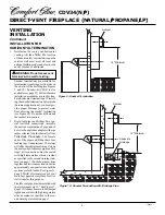
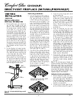
VENTING
INSTALLATION

Continued

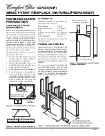
HIGH ALTITUDE INSTALLATION

Your Comfort Glow direct-vent fireplace
has been AGA tested and approved for
elevations from 0-2000 feet and CGA certi-
fied for elevations from 0-4500 feet.

When installing this fireplace at an elevation
above 2000 feet (in the USA), you may need
to decrease the input rating by changing the
existing burner orifice to a smaller size. Re-
duce input 4% for each 1000 feet above sea
level. Check with your  local gas company for
proper orifice size identification.

When installing this fireplace at an eleva-
tion above 4500 feet (in Canada), check
with local authorities.

Consult your local gas company to help de-
termine the proper orifice for your location.

For assistance with any high altitude instal-
lation contact DESA International’s Tech-
nical Services Department at 1-800-DESA-
LOG (1-800-337-2564).

PARTS LISTS FOR VENTING
KITS AND COMPONENTS

Comfort Glow Rigid Venting

Number Description

CBGFVK Basic Ground Floor Rigid

Vent Kit

Includes: 7" x 60

°

 Elbow, Extended

Adjustable Horizontal Termina-
tion, Wall Thimble and 14 Screws

CBVK

Basement Rigid Vent Kit

Includes: 7" x 30

°

 Elbow, 7" x 4'

Galvanized Pipe, 7" x 90

°

 Elbow,

7" Adjustable Galvanized Pipe (7-
12"), Wall Thimble, Horizontal
Termination, RTV Silicone and 20
Screws

CBVKA

Basement Rigid Vent Kit (Special)

Includes: 7" x 30

°

 Elbow, 7" x 4'

Galvanized Pipe, 7" x 90

°

 Elbow,

7" Adjustable Galvanized Pipe (7-
12"), RTV Silicone and 20 Screws

Number Description

CCVK

Corner Vent Kit

Includes: 7" x 30

°

 Elbow, 7" x 90

°

Elbow, 7" Adjustable Galvanized
Pipe (7-12"), Horizontal termina-
tion, wall thimble, 6" pipe, RTV
silicone and 20 screws

CSVK

Snorkel Rigid Vent Kit

Includes: 7" x 30

°

 Elbow, 7" x 4'

Galvanized Pipe, 7" x 90

°

 Elbow, 7"

Adjustable Galvanized Pipe (7-12"),
Wall Thimble, 36" Snorkel Termi-
nation, RTV Silicone and 28 Screws

CRVF

Roof Rigid Vent Kit

Includes: Flue Restrictor, Storm
Collar, 7" x 30

°

 Elbow, 7" x 4'

Galvanized Pipe, 7" x 2' Galvanized
Pipe, 7" Adjustable Galvanized Pipe
(7-12"), Firestop Support, Roof
Flashing, RTV Silicone, Vertical
Termination, and 26 screws.

CD1000 7" x 12" Galvanized Coaxial Pipe

(Qty 1)

CD1010 7" x 24" Galvanized Coaxial Pipe

(Qty 1)

CD1020 7" x 48" Galvanized Coaxial Pipe

(Qty 1)

CD1030 7" Adjustable (7-12") Galvanized

Coaxial Pipe (Qty 1)

CD1050 7" x 6" Galvanized Coaxial Pipe

(Qty 1)

CD2000 7" x 90

°

 Elbow (Qty 1)

CD2010 7" x 45

°

 Elbow (Qty 1)

CD2020 7" x 30

°

 Elbow (Qty 1)

CD2030 7" x 60

°

 Elbow (Qty 1)

CD3000 Wall Strap/Offset Support (Qty 1)

CD3010 Storm Collar (Qty 1)

CD3020 Wall Thimble (Qty 1)

CD3040  Vertical Termination Cap

CD3050 Vertical Restrictor (Qty 1)

CD3060 Ceiling Firestop/Support (Qty 1)

CD3070 Rectangular Horizontal Rigid

Vent Termination Cap

CD3090 Cathedral Ceiling Support Box

CD4000 Roof Flashing 6/12-9/12

CD4010 Roof Flashing 9/12-12/12

CD5000 Vinyl Siding Standoff (Qty 1)

Comfort Glow Rigid Venting 

(Cont.)

CBFGFVK Basic Flex Ground Floor Vent Kit

Includes: Flex Adapter, 7" x 2'
Flexible Pipe, 4" x 2' Flexible
Pipe, Wall Thimble, Horizontal
Termination, (2) Spacer Springs,
 (2) 4" Hose Clamps, (2) 7" Hose
Clamps, and 10 Screws

CFGFVK Flex Ground Floor Vent Ki

t

Includes: Flex Adapter, 7" x 4'
Flexible Pipe, 4" x 4' Flexible
Pipe, Wall Thimble, Horizontal
Termination, (4) Spacer Springs,
(2) 4" Hose Clamps, (2) 7" Hose
Clamps, RTV Silicone, and
10 Screws

CD1040

7" x 25' Coaxial Flex Pipe with
Spacer Springs

CD3080

Rectangular Horizontal Flex
Termination Cap

CD4020 Flex Connector (Qty 1)
CD4030 Flex Wall Thimble (Qty 1)
CD4040 4" Clamp (Qty 1)
CD4050 7" Clamp (Qty 1)

Summary of Contents for CDV34

Page 1: ...ect in stallation and operational procedures Forassistance or additional information consultaqualifiedinstaller service agency or the gas supplier This appliance may be installed in an aftermarket manufactured mobile home where not prohibited by state or local codes Aftermarket Completion of sale not for purpose of resale from the manufacturer WARNING If the information in this manual is not follo...

Page 2: ...ated on fire place nameplate 14 This appliance when installed must be electrically grounded in accordance with local codes or in the absence of local codes with the National Electri cal Code ANS NFPA 70 or the Cana dian Electrical Code CSA C22 1 15 Do not obstruct the flow of combus tion and ventilation air in any way Pro vide adequate clearances around air openings into the combustion chamber alo...

Page 3: ...o ignitor This sys tem requires no matches batteries or other sources to light fireplace Figure 1 Comfort Glow Direct Vent Fireplace CDV Series Glass Door Assembly Blower Adjustment Optional Installation ON OFF Remote Switch Optional Installation Piezo Ignitor Valve Pilot Assembly Log Set Grate Assembly Lava Rock Glowing Embers Top Louver Panel Lower Louver Panel Vent Opening Nailing Flange Stando...

Page 4: ...ce See Figure 3 20 34 3 4 5 8 for drywall facing Must maintain a minimum 1 clearance to combustibles 34 1 2 34 3 4 20 Vertical Termination 19 Horizontal Termination CLEARANCES Minimum clearances to combustibles for the fireplace are as follows Back and sides 0 mm Perpendicular walls 6 152mm Floor 0 mm Ceiling to louver opening 42 1067mm Front 36 914mm Top of Standoffs 0 mm See General Venting on p...

Page 5: ...s spe cifically approved for this fireplace Minimum clearance between vent pipes and combustible materials is 1 25 mm except where stated otherwise Combustible material may be flush with the top front of fireplace with a maxi mum thickness of 3 4 Do not recess venting terminals into a wall or siding Install horizontal venting with a 1 4 rise forevery12 ofruntowardthetermination You may paint the v...

Page 6: ...paved side walk or a paved driveway located on public property 84 inches 2133mm minimum M clearance under veranda porch deck 12 inches 305mm minimum N clearance above a roof shall extend a minimum of 24 inches 610mm above the highest point when it passes through the roof surface and any other obstruction within a horizontal distance of 18 inches 457mm vent shall not terminate directly above a side...

Page 7: ...e proper length of vent pipe for the type of termination you choose It is also important to note the wall thickness For Horizontal Termination Select the amount of vertical rise desired The horizon tal run of venting must have 1 4 rise for every 12 of run towards the termination NOTICE Treatment of firestops andconstructionofthechasemay varyfrombuildingtypetobuilding type These instructions are no...

Page 8: ...pipe and el bows to the appliance adaptor with pipe seams oriented towards the wall or floor Twist lock Procedure The female ends of the pipes and fittings have four locking lugs indentations These lugs will slide straight into matching slots on the male ends of adjacent pipes and fit tings All connections must be sealed with high temperature silicone sealant as specified in the second warning sta...

Page 9: ... cap Position the vent cap in the center of the 7 1 2 or 10 hole on the exterior wall with the arrow on the vent cap pointing up Insure proper clearance of 1 to combustibles is maintained At tach the vent cap with four wood screws supplied see Figure 13 Note Re place the wood screws with appropri ate fasteners for stucco brick concrete or other types of siding For vinyl siding use vinyl siding sta...

Page 10: ...x Note This configuration for use with corner installation UP Horizontal Venting See information in Figures 16 and 17 for Vertical V and Horizontal H maxi mums and minimums The same amounts apply for flexible venting CGFVK Vent Kit Shown recommended for use with cabinet mantels CBVK Vent Kit Shown Horizontal Termination Configurations Figures 16 through 20 show different con figurations for ventin...

Page 11: ... max 8 min 8 min 20 max 20 max 8 max 20 max Venting with Two 90 Elbows Vertical V Horizontal H1 Horizontal H2 5 min 6 max 6 min 12 max 7 min 18 max 8 min 20 max 20 max 20 max Figure 19 Horizontal Termination Configuration for Rigid Venting Using Two 90 Elbows Figure 20 Horizontal Termination Configuration for Rigid Venting Using Two 90 Elbows with Termination at 90 with Fireplace Continued ...

Page 12: ...spe cial attention to these installation in structions for required clearances air space to combustibles when passing through ceilings walls roofs enclo sures attic rafters etc Do not pack air spaces with insulation Also note maxi mum vertical rise of the venting sys tem and any maximum horizontal off set limitations Offsets must fall within the parameters shown in Figure 8 on page 6 2 Set the fir...

Page 13: ...sing a level Temporarily tack the support box in place through the inside walls and into the roof sheathing 4 Using tin snips cut the supportbox from the top corners down to the roofline and fold the resulting flaps over the roof sheathing see Figure 24 Apply a bead of non hardening mastic around the top edges of the support box to make a seal between the box and the roof Nail in place with roofin...

Page 14: ...ith No Horizontal Run VENTING INSTALLATION Continued Venting with Two 90 Elbows Vertical V1 Horizontal H 5 min 6 max 6 min 12 max 7 min 18 max 8 min 20 max Note Vertical V1 Vertical V2 20 max Figure 27 Vertical Rigid Venting Configuration Using Two 90 Elbows CRVF Kit Shown Note Restrictor must be installed in all vertical installations ...

Page 15: ...orizontal Termination RTVSiliconeand20 Screws CBVKA BasementRigidVentKit Special Includes 7 x 30 Elbow 7 x 4 Galvanized Pipe 7 x 90 Elbow 7 Adjustable Galvanized Pipe 7 12 RTV Silicone and 20 Screws Number Description CCVK Corner Vent Kit Includes 7 x 30 Elbow 7 x 90 Elbow 7 Adjustable Galvanized Pipe 7 12 Horizontal termina tion wall thimble 6 pipe RTV silicone and 20 screws CSVK Snorkel Rigid Ve...

Page 16: ...em scirculatingblowerwhile using heater This will help circu late the heat throughout the house In the event of a power outage you can use this heater as your primary heat source WARNING A qualified ser vicepersonmustinstallfireplace Follow all local codes CAUTION This fireplace cre ateswarmaircurrents Thesecur rents move heat to wall surfaces next to fireplace Installing fire place next to vinyl ...

Page 17: ...see Figure 33 Route power cord through both plastic bushing s and plug the power cord into a properly grounded 3 prong wall receptacle near the firebox b If your fireplace system installation is recessed and or pre wired a qualified installer must make all elec trical connections for the outlet kit included with the fireplace Figure 30 Mounting Blower to Firebox Top Mounting Tab Exhaust Port WARNI...

Page 18: ...r if allowed by local codes not provided AnA G A design certifiedmanualshutoff valve with 1 8 NPT tap is an acceptable alternative to test gauge connection Pur chase the A G A design certified manual shutoff valve from your retailer WARNING A qualified ser vice person must connect fire place to gas supply Follow all local codes CAUTION For propane LP units never connect heater di rectly to the pro...

Page 19: ...ings for leaks CHECKING GAS CONNECTIONS WARNING Test all gas pip ing and connections for leaks after installing or servicing Cor rect all leaks at once WARNING Neveruseanopen flame to check for a leak Apply commercial leak test solution to all gas joints Bubbles forming show a leak Correct all leaks at once Installation Items Needed 5 16 hex socket wrench or nut driver sealant resistant to propane...

Page 20: ...valve see Figure 37 2 Open propane LP supply tank valve for propane LP fireplace or main gas valve located on or near gas meter for natu ral gas fireplace 3 Make sure control knob of fireplace is in the OFF position 4 Check all joints from manual shutoff valve to thermostat gas valve see Fig ure 38 for propane LP or Figure 39 for natural Apply commercial leak test so lution to all gas joints Bubbl...

Page 21: ...housing 3 Replace battery cover onto remote con trol unit Figure 42 Installing Battery in Hand Held Remote Control Unit Battery Cover 9 Volt Battery Terminal Wires Remote Control Unit Battery Housing Figure 43 Removing Top Louver Panel Top Louver Panel 1 Remove the upper louver panel by lift ing upward and out see Figure 43 2 Remove the screws from the three tabs at the top of the glass door while...

Page 22: ... method described in step 3 6 Slide the right retainer bracket against the right side brick panel Loosely se cure the bracket screw This secures the right side brick panel 7 Install rear brick panel Rest bottom edge of panel on back edge of grate see Figure 46 Figure 45 Installing Left Side Brick Panel WARNING The glass door must be securely in place before running this fireplace Do not run thisfi...

Page 23: ... the front right part of the grate making sure the notches fit over the prong of the grate see Figure 50 6 Place lava rock along sides and front of inside of firebox bottom It is not necessary to use all of the lava rock provided 7 Pull ember material apart into pieces no larger than a dime Place these pieces loosely and sparingly directly onto the exposed section of the front burner and along the...

Page 24: ...cessing for lighting 8 Turn knob on gas control counter clockwise to PILOT 9 Push in control knob all the way and hold Immediately light the pilot by repeatedly depressing the piezo spark ignitor until a flame appears Continue to hold for about one 1 minute after the pilot is lit Release knob and it will pop back Pilot should remain lit If it goes out re peat steps 5 through 8 If knob does not pop...

Page 25: ... BURNER FLAME PATTERN Burner flames will be steady not lifting or floating Flame patterns will be different from unit to unit and will vary depending on installation type and weather conditions If the vent configuration is installed incor rectly the flames will lift or ghost This can be dangerous Inspect the flames after installationtoensureproperinstallationand performance Figure 55 shows a typic...

Page 26: ...dity WARNING Turn off fireplace and let cool before cleaning CAUTION Youmustkeepcon trol areas burners and circulat ing air passageways of fireplace clean Inspect these areas of fire place before each use Have fire place inspected yearly by a quali fiedserviceperson Fireplacemay need more frequent cleaning due to excessive lint from carpeting bedding material pet hair etc WARNING Do not use abra s...

Page 27: ...valve damaged REMEDY 1 Reconnect ignitor cable 2 Free ignitor cable if pinched by any metal or tubing Keep ignitor cable dry 3 Tighten nut holding piezo ignitor Nut is located behind the mounting bracket 4 Replace ignitor cable 5 Replace piezo ignitor 6 Replace pilot assembly 7 Replace pilot assembly 1 Turn on gas supply or open manual shutoff valve 2 Turn control knob to PILOT position 3 Press in...

Page 28: ...rner until air is removed from line Have gas line checked by local pro pane LP gas company 3 Clean burner see Cleaning and Mainte nance page 26 or replace burner orifice 1 Adjust the log set so that the flame does not excessively impinge on it 2 Inspect the opening at the base of the burner to see that it is NOT packed with any type of material 1 This is common If noise is excessive contact qualif...

Page 29: ... 2 Air holes at burner inlet blocked 3 Burner flame holes blocked OBSERVED PROBLEM Fireplace produces unwanted odors Fireplace shuts off in use Gas odor even when control knob is in OFF position Gas odor during combustion Dark residue on logs or inside of fireplace REMEDY 1 Locate and correct all leaks see Check ing Gas Connections pages 19 and 20 1 Fireplace has been tested for up to 40mph winds ...

Page 30: ...se only original replacement parts Thiswillprotectyourwarrantycoveragefor parts replaced under warranty PARTS UNDER WARRANTY Contact authorized retailers of this product If they can not supply original replacement part s call DESA International s Techni cal Service Department at 1 800 DESA LOG 1 800 337 2564 WhencallingDESAInternational haveready your name your address model and serial numbers of ...

Page 31: ...BLOWER KIT CDA3620T Provides better heat distribution Blower turns off and on automatically as needed Completeinstallationandoperationinstruc tions included in this manual DUPLEX OUTLET KIT GA3555 Not Shown Use for built in installations when hard wir ing a blower FIREPLACE SCREEN CDS34 For all models This fireplace screen easily attaches to the front glass panel with in cluded clips RECEIVER AND ...

Page 32: ...NE LP CDV34 N P 1 2 3 4 6 6 35 5 5 5 11 Included in Hardware Pack 7 7 8 10 9 12 13 14 15 16 17 18 19 20 32 21 22 23 24 25 26 27 28 28 29 30 31 1 31 4 31 2 31 3 33 32 32 34 46 36 37 39 38 42 40 41 6 44 43 45 ILLUSTRATED PARTS BREAKDOWN CDV34 N P A ...

Page 33: ...s manual KEY NO PART NUMBER DESCRIPTION QTY 1 104445 01 Top Outer Casing 34 1 2 105278 01 Outer Casing 34 1 3 105297 01 Bottom Outer Casing 1 4 104479 10BR Firebox Assembly 1 5 M11084 26 Screw Hex 50 6 M11084 46 Screw Hex 8 7 105394 01 Louver Extruded 2 8 104443 01 Firebox Support Right 1 9 104486 01 Firebox Support Left 1 10 104482 01 Switch Bracket 1 11 104483 01 Floor Mounting Bracket 2 12 1044...

Page 34: ...iring a defective heater will be the responsibility of the owner TOTHEFULLEXTENTALLOWEDBYTHELAWOFTHEJURISDICTIONTHATGOVERNSTHESALEOFTHEPRODUCT THIS EXPRESS WARRANTY EXCLUDES ANY AND ALL OTHER EXPRESSED WARRANTIES AND LIMITS THE DURA TION OF ANY AND ALL IMPLIED WARRANTIES INCLUDING WARRANTIES OF MERCHANTABILITY AND FITNESS FOR A PARTICULAR PURPOSE TO TWO 2 YEARS ON ALL COMPONENTS FROM THE DATE OF F...

Reviews: