


7
VFH InverterFlex
®
- Ductless Mini-Split
AITONS EQUIPMENT
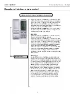
Features and functions of wireless remote control
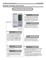
AUTO LOUVER SWING LEFT-RIGHT button
SWING UP AND DOWN button
SWING LEFT AND RIGHT button
Remote controller
OFF
OFF
•
Press swing left and right buttons continuously more than 2s
the lower will swing back and forth from the left to the right.
When you release the buttons the louver will stop swinging and
the present position of the louver will be kept.
• Press this button to set left & right swing angle cycling as shown below
.
comfortable position.
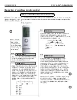
I FEEL
I FEEL button
it is more comfortable if the unit senses the
temperature at the level the remote sits,
rather that at the indoor unit, which is up
high on the wall. To select the sensing at
the remote control room temperature rather
than at the unit, press the I-FEEL button.
The I-FEEL icon will be displayed and the
temperature signal will be sent from the
remote to the unit every 10 minutes as long
as the remote controller is in range of the
indoor unit. To cancel, press the I-FEEL
button again.
• Press this button to set swing angle of the louve
r, which cycles
through the options below.
•
Adjust the swing
of the louver
to direct the air
comfortable
position.
•
This icon indicates that the
louver swings back and forth.
TIMER ON
TIMER ON button
•
The Timer feature is a program that can be
used to turn the unit on/off after a certain
amount of time has transpired. To set the
Timer on, press the Timer on button. The “ON”
icon will blink indicating that the program can
be set. Press the (+) or (-) buttons to adjust
the time duration in minutes. After the time
duration is set, press the Timer on button
again to begin the Timer on operation. To
cancel the Timer on operation, press the
Timer on button again.
No Te:
Be sure the clock is set to the actual
time before setting the timer. See clock
instructions to set the clock time.
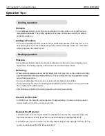
Operation of wireless remote control
TIMER OFF
TIMER OFF button
• Press the
Timer off button to create the timer off program. The
Timer off icon will blink, indicating it is in programming mode.
The set up process is the same as the timer on process - see
Timer On for instructions. The timer off program allows you to
determine when the unit should turn off based on how much
time has transpired.
AUTO LOUVER SWING button
• Press swing, + and - buttons continuously for more than
2s, the louver will swing back and forth when you release
the button, the louver will stop swinging and the present
position of the louver will be kept.