background image

507715-01

Page 1 of 61

Issue 1716

INSTALLATION INSTRUCTIONS

GUH95A & GUH92A

Warm Air Gas Furnace

Upflow/Horizontal Left and Right Air Discharge

Save these instructions for future reference


(P) 507715-01

*P507715-01*

Manufactured By

Comfort-Aire / Century

1900 Wellworth Ave.

Jackson, MI 49203

This manual must be left with the homeowner for future reference.

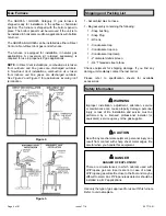
This is a safety alert symbol and should never be ignored. When you see this symbol on labels or in 

manuals, be alert to the potential for personal injury or death.

Improper  installation,  adjustment,  alteration,  service 

or maintenance can cause property damage, personal 

injury  or  loss  of  life.  Installation  and  service  must  be 

performed  by  a  licensed  professional  installer  (or 

equivalent), service agency or the gas supplier.

 WARNING

As with any mechanical equipment, personal injury can 

result from contact with sharp sheet metal edges. Be 

careful when you handle this equipment. 

 CAUTION

Table of Contents

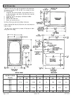
Unit Dimensions ..........................................................

2

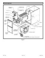
Parts Arrangement.......................................................

3

Gas Furnace

 ................................................................

4

Shipping and Packing List ...........................................

4

Safety Information .......................................................

4

General ........................................................................

6

Combustion, Dilution & Ventilation Air .........................

7

Installation .................................................................

10

Filters .........................................................................

13

Duct System ..............................................................

13

Venting Practices .......................................................

16

Condensate Piping ....................................................

36

Gas Piping

 .................................................................

39

Electrical ....................................................................

42

Unit Start-Up ..............................................................

45

Testing for Proper Venting and Sufficient Combustion 

Air for Non-Direct Vent Applications ..........................

49

Other Unit Adjustments..............................................

50

Blower Performance GUH92A ...................................

51

Blower Performance GUH95A ...................................

54

Service.......................................................................

56

Planned Service ........................................................

58

Repair Parts List ........................................................

58

Start-Up & Performance Checklist.............................

59

Summary of Contents for GUH92A

Page 1: ...lation and service must be performed by a licensed professional installer or equivalent service agency or the gas supplier WARNING As with any mechanical equipment personal injury can result from cont...

Page 2: ...l RAB Return Air Base 3 Bottom return air 4 Return air from both sides 5 Bottom and one side return air See Blower Performance tables for additional information 2 Optional External Side Return Air Fil...

Page 3: ...507715 01 Page 3 of 61 Issue 1716 Parts Arrangement Figure 1...

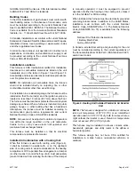
Page 4: ...1 Bag assembly containing the following 1 Snap bushing 1 Snap Plug 1 Wire tie 1 Condensate trap 1 Condensate trap cap 1 Condensate trap clamp 1 2 diameter debris screen 1 3 4 Threaded street elbow Ch...

Page 5: ...Fuel Gas Code or CSA B149 standards NOTE Furnace must be adjusted to obtain a temperature rise within the range specified on the unit nameplate Failure to do so may cause erratic limit operation and...

Page 6: ...a Construction Heater Gas furnaces manufactured on or after May 1 2017 are not permitted to be used in Canada for heating of buildings or structures under construction WARNING The following statement...

Page 7: ...ion from the National Fuel Gas Code ANSI Z223 1 NFPA 54 This reprinted material is not the complete and official position of ANSI on the referenced subject which is represented only by the standard in...

Page 8: ...e within 12 305 mm of the top of the enclosure and one within 12 305 mm of the bottom These openings must communicate directly or by ducts with the outdoors or spaces crawl or attic that freely commun...

Page 9: ...d Inlet Air Minimum 12 in 305mm above Crawl Space Floor Coupling or 3 in to 2 in Transition Field Provided See Maximum Vent Lengths table NOTE The inlet and outlet air openings shall each have a free...

Page 10: ...ace can result in personal injury or death Combustion and flue products must never be allowed to enter the return air system or air in the living space Use sheet metal screws and joint tape to seal re...

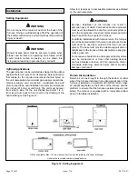
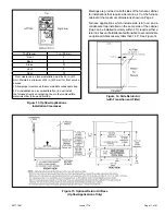
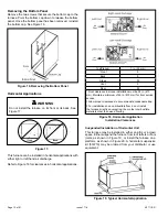
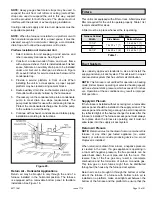
Page 11: ...combustible materials other than wood flooring Markings are provided on both sides of the furnace cabinet for installations that require side return air Cut the furnace cabinet at the maximum dimensi...

Page 12: ...ion Installation Clearances Top Plenum 1 in 25 mm Front 0 Back 0 Sides 0 Vent 0 Floor 0 Front clearance in alcove installation must be 24 in 610 mm Maintain a minimum of 24 in 610 mm for front service...

Page 13: ...unit is not equipped with a filter or rack Afield provided filter is required for the unit to operate properly Table 1 list recommended filter sizes A filter must be in place whenever the is operating...

Page 14: ...may be used for vent pipe hangers Uniformly apply a liberal coat of PVC primer for PVC or use a clean dry cloth for ABS to clean inside socket surface of fitting and male end of pipe to depth of fitt...

Page 15: ...er pipe is fully inserted to distribute cement evenly Do not turn ABS or cellular core pipe NOTE Assembly should be completed within 20 seconds after last application of cement Hammer blows should not...

Page 16: ...leakage corrosion or other deficiencies which could cause an unsafe condition 3 Close all building doors and windows and all doors between the space in which the appliances remaining connected to the...

Page 17: ...maximum pipe lengths permitted for GUH92A Table 6A through Table 6C list the maximum pipe lengths permitted for GUH95A Regardless of the diameter of pipe used the standard roof and wall terminations...

Page 18: ...ipe diameter Figure 24 045 070 090 110 Standard or Concentric See Table 3 Intake or Exhaust 2 2 1 2 or 3 Furnace capacity 1 Which termination 2 Which needs most elbows 3 How many 4 Desired pipe size 5...

Page 19: ...n a 97 97 78 78 74 9 36 21 70 55 23 92 92 73 73 69 10 31 16 65 50 18 87 87 68 68 64 Concentric Termination Elevation 0 10 000 ft Number of 90 Elbows Used 2 Pipe 2 1 2 Pipe 3 Pipe Capacity Capacity Cap...

Page 20: ...35 045 070 090 110 135 045 070 090 110 135 1 66 51 29 9 n a 95 80 48 23 n a 112 112 93 93 89 2 61 46 24 4 90 75 43 18 107 107 88 88 84 3 56 41 19 n a 85 70 38 13 102 102 83 83 79 4 51 36 14 80 65 33 8...

Page 21: ...7 97 78 78 74 9 36 21 70 55 23 92 92 73 73 69 10 31 16 65 50 18 87 87 68 68 64 Standard Termination Elevation 4 501 10 000 ft Number of 90 Elbows Used 2 Pipe 2 1 2 Pipe 3 Pipe Capacity Capacity Capaci...

Page 22: ...81 81 74 74 65 9 28 13 60 45 19 76 76 69 69 60 10 23 8 55 40 14 71 71 64 64 55 Concentric Termination Elevation 4 501 10 000 ft Number of 90 Elbows Used 2 Pipe 2 1 2 Pipe 3 Pipe Capacity Capacity Capa...

Page 23: ...65 43 8 83 82 63 63 59 8 31 16 60 60 38 3 78 77 58 58 54 9 26 11 55 55 33 n a 73 72 53 53 49 10 21 6 50 50 28 68 67 48 48 44 Standard Termination Elevation 4 501 10 000 ft Number of 90 Elbows Used 2 P...

Page 24: ...507715 01 Page 24 of 61 Issue 1716 Figure 25 Figure 26...

Page 25: ...he next two steps when installing the unit in Direct Vent applications where combustion air is taken from outdoors and flue gases are discharged outdoors The provided air intake screen must not be use...

Page 26: ...ward or to either side in the upflow position and either straight out or downward in the horizontal position Figure 30 The air intake piping must not terminate too close to the flooring or a platform...

Page 27: ...le 7 Maximum Allowable Exhaust Vent Pipe Length in ft without Insulation in Unconditioned Space for Winter Design Temperatures Single Stage High Efficiency Furnace Winter Design Temperatures1 F C Vent...

Page 28: ...e under veranda porch deck or balcony 12 Equal to or greater than soffit depth 3 feet 9m 12 3 feet 9m within a height 15 feet 4 5m above the meter regulator assembly 3 feet 9m 6 inches 152mm for appli...

Page 29: ...mm for appliances 10 000 pliances 10 000 Btuh 3kw and 50 000 pliances 50 000 Btuh 15kw 6 inches 152mm for appliances 10 000 Btuh 3kw 12 inches 305mm for appliances 10 000 Btuh 3kw and 100 000 Btuh 30k...

Page 30: ...rnational B149 installation codes the minimum allowed distance between the combustion air intake inlet and the exhaust outlet of other appliances shall not be less than 12 inches 305 mm IMPORTANT Deta...

Page 31: ...ke and exhaust piping must be run up a side wall to position above snow accumulation or other obstructions piping must be supported every 24 610 mm as shown in Figure 44 Exhaust and intake piping that...

Page 32: ...ITTINGS PROVIDE SUPPORT OF PIPE ON TOP PLATE ALTERNATE INTAKE PIPE INTAKE PIPE INSULATION optional EXTERIOR PORTION OF CHIMNEY INSULATE TO FORM SEAL SHEET METAL TOP PLATE Minimum 12 305MM above chimne...

Page 33: ...grade or average snow accumulation B Horizontal separation between intake and exhaust C Minimum from end of exhaust to inlet of intake D Exhaust pipe length E Wall support distance from top of each pi...

Page 34: ...Kit 15F75 or 44J41 UNCONDITIONED ATTIC SPACE 3 76MM OR 2 51MM PVC PROVIDE SUPPORT FOR EXHAUST LINES 12 305MM ABOVE AVE SNOW ACCUMULATION SIZE PER EXHAUST PIPE TERMINATION SIZE REDUCTION TABLE Figure...

Page 35: ...e To Vent Termination Drain Trap assembled Figure 49 Kit 51W18 Parts Identification and Assembly Exhaust from Furnace To Termination Exhaust from Furnace To Termination Figure 50 Kit 51W18 Trap Assemb...

Page 36: ...ittings glue all joints Glue the provided drain trap as shown in Figure 58 Route the condensate line to an open drain Condensate line must maintain a 1 4 downward slope from the furnace to the drain D...

Page 37: ...iping from furnace must slope down a minimum of 1 4 per ft toward trap Figure 55 Evaporator Coil Using a Separate Drain Figure 56 Evaporator Coil Using a Common Drain Piping from furnace must slope do...

Page 38: ...507715 01 Page 38 of 61 Issue 1716 Figure 58 Trap Drain Assembly Using 1 2 PVC or 3 4 PVC...

Page 39: ...r gas vents dumb waiters or elevator shafts Center gas line through piping hole Gas line should not touch side of unit See Figure 61 and Figure 62 4 Piping should be sloped 1 4 per 15 feet 6 mm per 5...

Page 40: ...the safety warnings exactly could result in serious injury death or property damage Never use an open flame to test for gas leaks Check all connections using a commercially available soap solution mad...

Page 41: ...16 42 530 15 01 490 13 87 460 13 03 430 12 18 400 11 33 1 1 2 38 1 1 610 40 894 2100 59 46 460 41 34 1180 33 41 990 28 03 900 25 48 810 22 94 750 21 24 690 19 54 650 18 41 620 17 56 2 50 8 2 067 52 50...

Page 42: ...t check to make sure the wires will be long enough for servicing at a later date Make sure that thermostat wire is long enough to facilitate future removal of blower for service Complete the wiring co...

Page 43: ...ndoor blower will run continuously on the heating speed when there is no cooling or heating demand 2 When the furnace is running in the heating mode the indoor blower will run on the heating speed 3 W...

Page 44: ...ssue 1716 045 2 045 3 070 2 070 3 090 3 090 4 110 4 110 5 135 5 DO NOT USE RED LOW SPD MOTOR LEAD FOR HEATING LEAVE ON PARK TERMINAL FOR 070B2 070BP2 090C3 090CP3 110C4 110CP4 135D5 AND 135DP5 Figure...

Page 45: ...r property damage Should the gas supply fail to shut off or if overheating occurs shut off the gas valve to the furnace before shutting off the electrical blower deck before performing any service pro...

Page 46: ...r to the unit 11 Set the thermostat to desired setting NOTE When unit is initially started steps 1 through 11 may need to be repeated to purge air from gas line 12 If the appliance will not operate fo...

Page 47: ...r the unit to stabilize observe the flame Flame should be stable and should not lift from burner Natural gas should burn blue 4 After allowing unit to stabilize for 5 minutes record manifold pressure...

Page 48: ...ts at Varying Altitudes Capacity 0 4500 ft 0 1371m 4501 7500 ft 1371 2286m 7501 10000 ft 2286 3048m 045 No Change 11J09 11J10 070 090 110 135 No Change 11J11 11U68 Pressure switch is factory set No ad...

Page 49: ...2 Visually inspect the venting system for proper size and horizontal pitch Determine there is no blockage or restriction leakage corrosion or other deficiencies which could cause an unsafe condition 3...

Page 50: ...ostat Heat Anticipation Set the heat anticipator setting if adjustable according to the amp draw listed on the wiring diagram that is attached to the unit Electrical 1 Check all wiring for loose conne...

Page 51: ...1160 475 1005 400 0 10 1600 685 1355 565 1155 465 1015 390 0 20 1550 650 1330 540 1150 445 1000 380 0 30 1480 625 1295 515 1140 430 975 365 0 40 1425 590 1280 490 1105 415 975 350 0 50 1355 565 1190 4...

Page 52: ...0 10 1610 720 1335 595 1135 490 975 395 0 20 1565 695 1335 565 1145 465 970 385 0 30 1525 665 1300 555 1135 455 970 370 0 40 1485 635 1295 520 1110 435 960 355 0 50 1430 600 1260 495 1090 405 940 345...

Page 53: ...765 1545 640 2160 1200 1995 975 1755 795 1510 650 0 60 2020 1100 1865 885 1721 745 1485 615 2065 1155 1875 925 1690 770 1455 630 0 70 1910 1065 1765 855 1630 720 1425 600 1945 1100 1800 900 1595 735...

Page 54: ...50 550 0 10 2110 850 1880 760 1585 635 1360 545 0 20 2060 810 1835 725 1580 620 1360 520 0 30 1990 765 1805 690 1550 585 1365 495 0 40 1925 750 1755 655 1510 545 1330 470 0 50 1830 700 1680 610 1455 5...

Page 55: ...650 1060 1430 865 1360 710 1210 595 1575 1035 1530 850 1250 705 1125 585 NOTE All air is measured external to unit without filter filter not furnished field provided GUH95A 110 C5 Performance Less Fil...

Page 56: ...to empty condensate water 3 Remove the clean out cap from the condensate trap and empty water Inspect the trap then reinstall the clean out cap Cleaning Heat Exchanger If cleaning the heat exchanger...

Page 57: ...he 2 pin plug to the wire harness 38 Reconnect drain tubes between flue collar and cold end header box 39 Secure burner assembly to vestibule panel using four existing screws Burners are self aligning...

Page 58: ...hat may result in unsafe operation For instance items innocently stored next to the furnace may obstruct the combustion air supply This could cause incomplete combustion and the production of carbon m...

Page 59: ...ondensate Trap Primed Line Sloped Heat Cable Installed and Operable if applicable 2 2 2 1 Horizontal Pipes Sloped if applicable UNIT SET UP 3 4 Flter RETURN AIR Furnace Model Number_______________ Ser...

Page 60: ...C 5 Supply External Static _______ Return External Static ______ Total External Static _______ CONDENSATE LINE 6 Leak Free VENT PIPE 7 Leak Free COOLING MODE INDOOR BLOWER AMPS______ 3 TEMPERATURE DRO...

Page 61: ...height of eight 8 feet above grade directly in line with the exhaust vent terminal for the horizontally vented gas fueled heating appliance or equipment The sign shall read in print size no less than...

Reviews: