


507868-02P
Page 46 of 48
Issue 1922
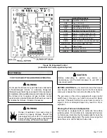
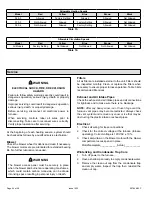
Table 17. Control Diagnostic Codes
Integrated Control LED Codes
Red LED Flash Code
2
Diagnostic Codes / Status of Furnace
LED Off
No power to control or control hardware fault detected
Heartbeat
1
Normal operation - idle, continuous fan, cool
Continuous Rapid Flash Call for heat / burner operation
1 Flash
Reverse line voltage polarity
2 Flashes
Improper earth ground
3 Flashes
Burner failed to light, or lost flame during heat demand
4 Flashes
Low flame signal - check flame sensor
5 Flashes
Watchguard - burner failed to light, exceeded maximum number of retries or recycles
6 Flashes
Not used
7 Flashes
Primary or Secondary limit open or watchguard mode - limit switch open longer than 3 minutes
8 Flashes
Rollout switch open
9 Flashes
Pressure switch failed to close or opened during heat demand
10 Flashes
Watchguard - Pressure switch opened 5 times during one heat demand
11 Flashes
Pressure switch stuck closed prior to activation of combustion air inducer
12 Flashes
Flame sensed without gas valve energized
13 Flashes
Low line voltage
1
A “heartbeat” is indicated by a “slow flash” - 1 sec on 1 sec off, repeating
2
Error codes are indicated by a “rapid flash” - the LED flashes X times at 1/2 sec on, 1/2 sec off, remains off for 3 sec, then repeats
NOTE
: Last 10 error codes are stored in memory, including when power is shut off to the unit. To recall, press and release button.
Most recent will be displayed first, LED off for 3 sec, then next error code is displayed, etc. To clear error codes, depress and hold
button longer than 5 seconds.
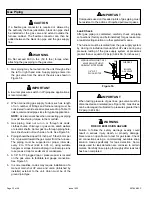
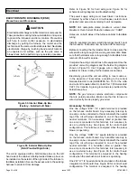
Cleaning the Burner Assembly
1. Turn off electrical and gas power supplies to furnace.
Remove upper and lower furnace access panels.
2. Disconnect the 2 pin plug from the gas valve.
3. Remove the burner box cover.
4. Disconnect the gas supply line from the gas valve.
Remove gas valve/manifold assembly.
5. Mark and disconnect sensor wire from the sensor.
Disconnect 2 pin plug from the ignitor at the burner
box.
6. Remove four screws which secure burner box
assembly to vest panel. Remove burner box from the
unit.
7. Use the soft brush attachment on a vacuum cleaner
to gently clean the face of the burners. Visually
inspect the inside of the burners and crossovers for
any blockage caused by foreign matter. Remove any
blockage.
8. Reconnect the sensor wire and reconnect the 2 pin
plug to the ignitor wiring harness.
9. Reinstall the burner box assembly using the existing
four screws. Make sure that the burners line up in the
center of the burner ports.
10. Reinstall the gas valve manifold assembly. Reconnect
the gas supply line to the gas valve. Reinstall the
burner box cover.
11. Reconnect 2 pin plug to gas valve.
12. Replace the blower compartment access panel.
13. Refer to instruction on verifying gas and electrical
connections when re-establishing supplies.
14. Follow lighting instructions to light and operate furnace
for 5 minutes to ensure that heat exchanger is clean
and dry and that furnace is operating properly.
15. Replace heating compartment access panel.