background image

507961-01P

Page 17 of 58

Issue 1933

1.  Seal  any  unused  openings  in  the  common  venting 

system.

2.  Inspect  the  venting  system  for  proper  size  and 

horizontal pitch. Determine that there is no blockage, 

restriction,  leakage,  corrosion,  or  other  deficiencies 

which could cause an unsafe condition. 

3.  Close  all  building  doors  and  windows  and  all  doors 

between the space in which the appliances remaining 

connected to the common venting system are located 

and  other  spaces  of  the  building.  Turn  on  clothes 

dryers  and  any  appliances  not  connected  to  the 

common venting system. Turn on any exhaust fans, 

such as range hoods and bathroom exhausts, so they 

will  operate  at  maximum  speed.  Do  not  operate  a 

summer exhaust fan. Close fireplace dampers. 

4.  Follow the lighting instructions. Turn on the appliance 

that is being inspected. Adjust the thermostat so that 

the appliance operates continuously. 

5.  After the main burner has operated for 5 minutes, test 

for leaks of flue gases at the draft hood relief opening. 

Use the flame of a match or candle. 

6.  After  determining  that  each  appliance  connected  to 

the common venting system is venting properly, (step 

3)  return  all  doors,  widows,  exhaust  fans,  fireplace 

dampers,  and  any  other  gas  burning  appliances  to 

their previous mode of operation.

7.  If  a  venting  problem  is  found  during  any  of  the 

preceding tests, the common venting system must be 

modified to correct the problem. 

8.  Resize the common venting system to the minimum 

vent  pipe  size  determined  by  using  the  appropriate 

tables  in  Appendix  G.  (These  are  in  the  current 

standards  of  the  National  Fuel  Gas  Code  ANSI 

Z223.1.) 

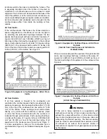
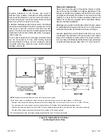
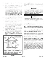
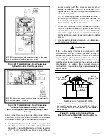
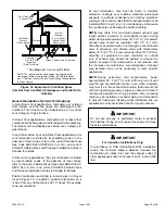
Figure 22. 

If this gas furnace replaces a furnace which was commonly vented 

with another gas appliance, the size of the existing vent pipe for 

that gas appliance must be checked. Without the heat of the original 

furnace flue products, the existing vent pipe is probably oversized 

for the single water heater or other appliance. The vent should be 

checked for proper draw with the remaining appliance.

Exhaust Piping

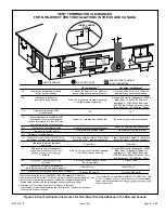
Route  piping  to  outside  of  structure.  Continue  with 

installation following instructions given in piping termination 

section.

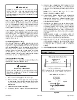
Do  Not  discharge  exhaust  into  an  existing  stack  or 

stack that also serves another gas appliance. If vertical 

discharge through an existing unused stack is required, 

insert PVC pipe inside the stack until the end is even 

with the top or outlet end of the metal stack. 

   CAUTION

The exhaust vent pipe operates under positive pressure 

and must be completely sealed to prevent leakage of 

combustion products into the living space.

   CAUTION

Vent Piping Guidelines

This gas furnace can be installed as either Non-Direct Vent 

or a Direct Vent gas central furnace.

NOTE: 

In Non-Direct Vent installations, combustion air is 

taken from indoors and flue gases are discharged outdoors.

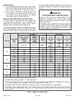
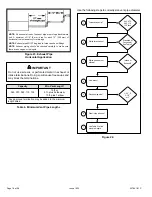
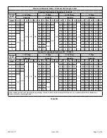
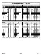
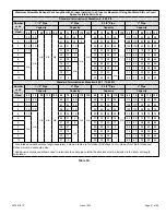
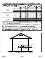
Intake  and  exhaust  pipe  sizing  -  Size  pipe  according  to 

Table 4 and Table 5A through Table 5C. Table 4 lists the 

minimum  vent  pipe  lengths  permitted.  Table  5A  through 

Table 5C lists the maximum pipe lengths permitted.

Regardless of the diameter of pipe used, the standard roof 

and wall terminations described in section Exhaust Piping 

Terminations  should  be  used.  Exhaust  vent  termination 

pipe is sized to optimize the velocity of the exhaust gas as 

it exits the termination. Refer to Table 7.

In  some  applications  which  permit  the  use  of  several 

different sizes of vent pipe, a combination vent pipe may 

be used. Contact Comfort-Aire / Century for assistance in 

sizing vent pipe in these applications.

NOTE: 

The  exhaust  collar  on  all  models  is  sized  to 

accommodate  2”  Schedule  40  vent  pipe.  When  vent 

pipe  which  is  larger  than  2”  must  be  used  in  an  upflow 

application,  a  transition  must  be  applied  at  the  exhaust 

collar in order to properly step to the larger diameter vent 

pipe. Contact Comfort-Aire / Century 

for more information 

concerning sizing of vent systems which include multiple 

pipe sizes.

Summary of Contents for 045-3

Page 1: ...llation adjustment alteration service or maintenance can cause property damage personal injury or loss of life Installation and service must be performed by a licensed professional installer or equiva...

Page 2: ...ptional RAB Return Air Base 3 Bottom return air 4 Return air from both sides 5 Bottom and one side return air 2 Optional External Side Return Air Filter kit is not for use with optional Return Air Bas...

Page 3: ...507961 01P Page 3 of 58 Issue 1933 Figure 1 Parts Arrangement...

Page 4: ...following 1 Snap bushing 1 Snap Plug 1 Wire tie 1 Condensate trap 1 Condensate trap cap 1 Condensate trap clamp 1 2 Diameter debris screen 1 3 4 Threaded street elbow Check equipment for shipping dama...

Page 5: ...obtain a temperature rise within the range specified on the unit nameplate Failure to do so may cause erratic limit operation and premature heat exchanger failure This furnace must be installed so th...

Page 6: ...TO FOLLOW THE ABOVE INSTALLATION INSTRUCTIONS FAILURE TO FOLLOW THE ABOVE INSTALLATION INSTRUCTIONS VOIDS THE MANUFACTURER S EQUIPMENT LIMITED WARRANTY COMFORT AIRE CENTURY DISCLAIMS ALL LIABILITY IN...

Page 7: ...position of ANSI on the referenced subject which is represented only by the standard in its entirely In Canada refer to the CSA B149 Installation codes Do not install the furnace in a corrosive or con...

Page 8: ...g shall be within 12 305 mm of the top of the enclosure and one within 12 305 mm of the bottom These openings must communicate directly or by ducts with the outdoors or spaces crawl or attic that free...

Page 9: ...tal louvers and grilles will have 60 to 75 percent free area Louvers and grilles must be fixed in the open position or interlocked with the equipment so that they are opened automatically during equip...

Page 10: ...rap and drain connections and installation and service clearances 24 inches 610 mm at unit front The unit must be level from side to side Tilt the unit slightly maximum 1 2 in from level from back to...

Page 11: ...The furnace is equipped with a removable bottom panel to facilitate installation Markings are provided on both sides of the furnace cabinet for installations that require side return air Cut the furna...

Page 12: ...installed in horizontal applications with either right or left hand air discharge Refer to Figure 18 for clearances in horizontal applications Figure 18 Horizontal Application Installation Clearances...

Page 13: ...f unit is installed above finished space fabricate an auxiliary drain pan to be installed under unit Set unit in drain pan as shown in Figure 20 Leave 8 inches for service clearance below unit for con...

Page 14: ...quivalent sealing method between the plenum and the furnace cabinet to ensure a tight seal If a filter is installed size the return air duct to fit the filter frame Pipe Fittings Specifications All pi...

Page 15: ...nutes before placing unit into operation DANGER 1 Measure and cut vent pipe to desired length 2 Debur and chamfer end of pipe removing any ridges or rough edges If end is not chamfered edge of pipe ma...

Page 16: ...he venting system being placed into operation while all other appliances connected to the venting system are not in operation WARNING Capacity VENT PIPE DIA in STANDARD CONCENTRIC Outdoor Exhaust Acce...

Page 17: ...nt pipe is probably oversized for the single water heater or other appliance The vent should be checked for proper draw with the remaining appliance Exhaust Piping Route piping to outside of structure...

Page 18: ...al in exhaust or intake terminations Doing so will cause freeze ups and may block the terminations IMPORTANT Table 4 Minimum Vent Pipe Lengths Capacity Min Vent Length 045 070 090 110 135 15 ft or 5 f...

Page 19: ...6 21 70 70 48 13 93 92 73 73 69 10 31 16 65 65 43 8 88 87 68 68 64 Standard Termination Elevation 4 501 10 000 ft Number of 90 Elbows Used 1 1 2 Pipe 2 Pipe 2 1 2 Pipe 3 Pipe Capacity Capacity Capacit...

Page 20: ...8 13 60 60 44 9 76 76 69 69 60 10 23 8 55 55 39 n a 71 71 64 64 55 Concentric Termination Elevation 4 501 10 000 ft Number of 90 Elbows Used 1 1 2 Pipe 2 Pipe 2 1 2 Pipe 3 Pipe Capacity Capacity Capac...

Page 21: ...53 49 10 21 6 50 50 28 68 67 48 48 44 Standard Termination at Elevation 4 501 10 000 ft Number of 90 Elbows Used 1 1 2 Pipe 2 Pipe 2 1 2 Pipe 3 Pipe Capacity Capacity Capacity Capacity 45 70 90 110 1...

Page 22: ...t Applications TYPICAL EXHAUST PIPE CONNECTIONS IN HORIZONTAL DIRECT OR NON DIRECT VENT APPLICATIONS RIGHT HAND DISCHARGE SHOWN SIDE VIEW 45 MAX 45 MAX 2 2 2 2 or 2 12 max EXHAUST TRANSITION 3 2 2 EXH...

Page 23: ...Discharge Shown Intake Piping Figure 27 through Figure 30 This gas furnace may be installed in either direct vent or non direct vent applications In non direct vent applications when intake air will...

Page 24: ...ill not be obstructed by loose insulation or other items that may clog the debris screen 2 If intake air is drawn from a ventilated attic Figure 31 or ventilated crawlspace Figure 32 the exhaust vent...

Page 25: ...ons and 12 above the average snow accumulation At vent termination care must be taken to maintain protective coatings over building materials prolonged exposure to exhaust condensate can destroy prote...

Page 26: ...A 3 in N A N A N A N A 8 8 7 7 13 13 1 Refer to 99 Minimum Design Temperature table provided in the current edition of the ASHRAE Fundamentals Handbook 2 Poly Propylene vent pipe PP by Duravent and C...

Page 27: ...randa porch deck or balcony 12 Equal to or greater than soffit depth 3 feet 9m 12 3 feet 9m within a height 15 feet 4 5m above the meter regulator assembly 3 feet 9m 6 inches 152mm for appliances 10 0...

Page 28: ...iances 10 000 pliances 10 000 Btuh 3kw and 50 000 pliances 50 000 Btuh 15kw 6 inches 152mm for appliances 10 000 Btuh 3kw 12 inches 305mm for appliances 10 000 Btuh 3kw and 100 000 Btuh 30kw 36 inches...

Page 29: ...f terminations and 6 152 mm on sidewall terminations 3 On roof terminations the intake piping should terminate straight down using two 90 elbows see Figure 36 4 Exhaust piping must terminate straight...

Page 30: ...t Concentric Wall Termination 71M80 69M29 OR 60L46 US 41W92 or 41W93 Canada Figure 42 Optional Vent Termination for Multiple Unit Installation of Direct Vent Wall Termination Figure 43 Direct Vent App...

Page 31: ...grade or average snow accumulation B Horizontal separation between intake and exhaust C Minimum from end of exhaust to inlet of intake D Exhaust pipe length E Wall support distance from top of each p...

Page 32: ...R EXHAUST LINES 12 305MM ABOVE AVE SNOW ACCUMULATION SIZE PER EXHAUST PIPE TERMINATION SIZE REDUCTION TABLE Figure 46 Non Direct Vent Field Supplied Wall Termination SIZE TERMINATION PER EXHAUST PIPE...

Page 33: ...ermination Drain Trap assembled Figure 49 Kit 51W18 USA 15Z70 Canada Parts Identification and Assembly Exhaust from Furnace To Termination Exhaust from Furnace To Termination Kit 51W18 is shown Figure...

Page 34: ...o not use copper tubing or existing copper condensate lines for drain line CAUTION 5 Figure 54 and Figure 55 show the furnace and evaporator coil using a separate drain If necessary the condensate lin...

Page 35: ...ion using a separate drain Piping from furnace must slope down a minimum of 1 4 per ft toward trap Figure 55 Unit with Evaporator Coil Using a Separate Drain Figure 56 Evaporator Coil Using a Common D...

Page 36: ...507961 01P Page 36 of 58 Issue 1933 Figure 58 Trap Drain Assembly Using 1 2 PVC or 3 4 PVC...

Page 37: ...n in or through air ducts clothes chutes chimneys or gas vents dumb waiters or elevator shafts Center gas line through piping hole Gas line should not touch side of unit See Figure 60 and Figure 61 4...

Page 38: ...ND INSTALLED GROUND JOINT UNION DRIP LEG MANUAL MAIN SHUT OFF VALVE Horizontal Application Right Side Air Discharge Gas Valve GROUND JOINT UNION DRIP LEG MANUAL MAIN SHUT OFF VALVE GROUND JOINT UNION...

Page 39: ...16 42 530 15 01 490 13 87 460 13 03 430 12 18 400 11 33 1 1 2 38 1 1 610 40 894 2100 59 46 460 41 34 1180 33 41 990 28 03 900 25 48 810 22 94 750 21 24 690 19 54 650 18 41 620 17 56 2 50 8 2 067 52 5...

Page 40: ...t switch near the furnace so that power can be turned off for servicing Table 9 Capacity Maximum Over Current Protection Amps 045B3 070B3 090C3 15 090C5 110C5 135D5 20 4 Before connecting the thermost...

Page 41: ...thermostat the wiring to be done and any replacement of wire shall conform with the temperature limitation for Type T wire 63 F 35 C rise Connect a sufficiently sized wire with ground to the furnace s...

Page 42: ...s a call for dehumidification Both the passive and active dehumidification methods described above can be utilized on the same furnace Circulating Airflow Adjustments Cooling Mode The units are factor...

Page 43: ...blower remains energized until the limits are closed Fan On When the thermostat is set for continuous fan operation and there is no demand for heating or cooling a call for fan closes the R to G circu...

Page 44: ...W1 W2 Heat Call Figure 68 Indoor Blower Operation High Heat W2 Call Figure 69 Indoor Blower Operation Call for Fan Percentage of High Stage Cooling Figure 70 Indoor Blower Operation Single Stage Cool...

Page 45: ...hown by a red LED on the control board The control continuously monitors its own operation and the operation of the system If a failure occurs the LED will indicate the failure code The flash codes ar...

Page 46: ...USE INJURY OR DEATH UNIT MUST BE GROUNDED IN ACCORDANCE WITH NATIONAL AND LOCAL CODES NOTE IF ANY WIRE IN THIS APPLIANCE IS REPLACED IT MUST BE REPLACED WITH WIRE OF LIKE SIZE RATING INSULATION THICKN...

Page 47: ...G MATERIAL HAVING A TEMP RATING OF AT LEAST 90 c 3 PROPER POLARITY MUST BE OBSERVED FOR FIELD LINE VOLTAGE SUPPLY IGNITION CONTROL WILL LOCK OUT IF POLARITY IS REVERSED 4 FOR TEMPORARY SERVICE REPLACE...

Page 48: ...075 1210 1370 Normal 815 980 1120 1255 720 885 1020 1135 1st Stage 595 760 865 980 Normal 540 660 785 890 485 600 695 790 GUH96T070B3M Temp Rise Speed Adjustment Heating CFM 0 0 8 w c Setting D Settin...

Page 49: ...Normal 800 945 1100 1245 720 840 970 1115 1st Stage 625 710 830 950 Normal 565 670 760 860 520 610 685 785 GUH96T090C5M Temp Rise Speed Adjustment Heating CFM 0 0 8 w c Setting D Setting C Setting B...

Page 50: ...rmal 1220 1405 1570 1795 1075 1270 1430 1635 1st Stage 935 1065 1245 1405 Normal 865 970 1145 1280 790 890 1025 1165 GUH96T135D5M Temp Rise Speed Adjustment Heating CFM 0 0 8 w c Setting D Setting C S...

Page 51: ...Allowed Allowed Allowed Allowed Norm Allowed Allowed Factory Setting Allowed 10 Allowed Allowed Allowed Allowed GUH96T090C5M 10 Allowed Allowed Allowed Allowed Norm Allowed Allowed Factory Setting Al...

Page 52: ...ight burners on this furnace Each time the thermostat calls for heat the burners will automatically light The ignitor does not get hot when there is no call for heat on these units Gas Valve Operation...

Page 53: ...nt Gas Flow Approximate Capacity Seconds for One Revolution Natural LP 1 cu ft Dial 2 cu ft Dial 1 cu ft Dial 2 cu ft Dial 045 80 160 200 400 70 55 110 136 272 90 41 82 102 204 110 33 66 82 164 135 27...

Page 54: ...reset switches are located on the front of the burner box Pressure Switch The pressure switch is located in the heating compartment on the cold end header box This switch checks for proper combustion...

Page 55: ...f power to the furnace 2 Have a shallow pan ready to empty condensate water 3 Remove the clean out cap from the condensate trap and empty water Inspect the trap then reinstall the clean out cap Cleani...

Page 56: ...on box 37 Reinstall the combustion air inducer and flexible no hub connector Reconnect the 2 pin plug to the wire harness 38 Reconnect drain tubes between flue collar and cold end header box 39 Secure...

Page 57: ...Problems detected during the inspection may make it necessary to temporarily shut down the furnace until the items can be repaired or replaced Instruct the homeowners to pay attention to their furnace...

Page 58: ...height of eight 8 feet above grade directly in line with the exhaust vent terminal for the horizontally vented gas fueled heating appliance or equipment The sign shall read in print size no less than...

Reviews: