©COMEV
AL
V
AL
VE SYSTEMS
Technical Dept. Ref. IOM - DUAL
PLA
TE CHECK V
AL
VES, UNIFLOW DC/DP
- Ed.20/07
Comeval V
alve Systems reserves the right to alter any technical data contained in this manual without prior notice. Regularly updated data on www
.comeval.es
Page 3
IOM - DUAL PLATE CHECK VALVES AND DISC
UNIFLOW DC/DP
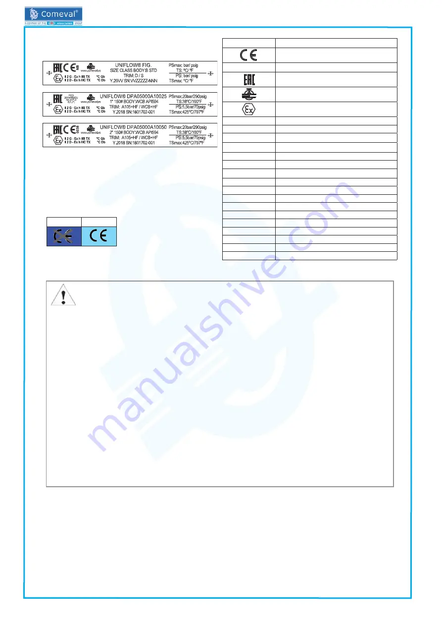
4.4 Marking/nameplate
Nameplate description of the valve:
4.5 CE marking.
5. INSTALLATION
5.1 General remarks on installation
The following points should be taken into account in addition to the general principles governing installation work:
ATTENTION!
- Remove remaining packing/storage protection if present.
- The interior of the valve and the pipeline must be free of foreign particles.
- Follow the arrow in the body for normal flow direction for installation. If the valve is in horizontal pipeline, the shaft
must be in the vertical position for correct operation.
- Lay pipelines such that damaging transverse, bending and torsional forces are avoided.
- Protect valves from dirt during construction work.
- Protect the valve soft parts, if any, from heating caused by welding works at the plant during commissioning.
- Suitable materials handling and lifting equipment should be used for assembly work. During assembly work, ensu-
re that the valve is fixed adequately. See data sheet for weights.
- The valves can be assembled vertically on horizontal pipeline or horizontally on vertical pipeline with normal flow
upwards.
- You must only operate the unmounted valve while observing all the safety measures.
- Avoid mechanical damage to the seat during handling, storage and installation.
- There is a crushing hazard between the discs or plates and the seat. Ensure the discs are in rest position in case
a hand is introduced inside the valve.
- Install the valves always between flanges, using suitable gaskets provided with the valve. Be sure that the contact
faces are free of impurities or fluid residues that may compromise the tightness.
- In order to fit a wafer type valve between flanges, centre the valve between flanges, insert one or two stud bolts
depending on the size and tighten them with nuts without forcing. Once the valve preliminary fitted, insert the rest of
stud bolts. Tighten nuts diagonally and gradually. Tighten again during start-up if necessary. For lug type, procedure
is similar but all holes of the valve are threaded, so that threaded bolts are used instead of stud bolts and nuts.Valve
should fit smoothly between flanges without building any tension.
DN≤25
DN>25
Mark
Description
CE-Marking
NB
Number of notify body
EAC marking (compliance with
TR/CU 032/2013 & TR CU 010/2011)
Manufacturer logo
Explosion protected mark for EU free
circulation (see separate instructions for code)
www.comeval.es
Website of manufacturer
UNIFLOW®
Brand
PED 2014/68/EU
Directive 2014/68/EU
FIG.
Valve code*
SEP
Sound Engineering Practice
Y.20VV
Manufacturing year
SN: VVZZZZZ-N
Batch / Serial no.
SIZE
Valve size
CLASS
Valve class
B
Body material
STD
Main manufacturing standard
D
Disc material
S
Seat material
PSmax
Max. pressure
TS
Max. temperature at max. pressure
PS
Max. pressure at max. temperature
TSmax
Max. temperature
* See coding system on Data Sheet.


