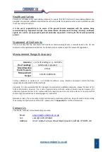
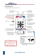
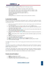
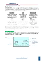
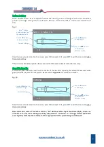
Comdronic AC7 Operating Instructions Manual Download Page 8


www.comdronic.co.uk 

Fig. 2 


*

If the measured 

Δp

 reaches the design 

Δp

 for the selected valve, the flow status message will be 

FLOW OK

However, if the design 

Δp

 is not met the flow status message will be 

LOW FLOW


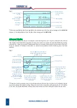
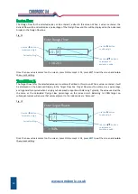
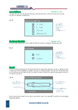
The  Advanced  Display  can  show  more  complex  commissioning  data  and  it  may  be  preferred  to  the  DP  And 
Flow Display if automatic balancing valves are being measured or if a system of proportional balancing is being 
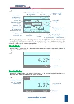
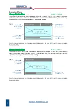
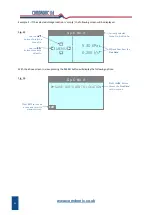
adopted. Fig. 3 shows an example of displayed data when a variable orifice valve has been selected and fig. 4 
shows  an  example  of  displayed  data  when  an  externally  adjustable  automatic  balancing  valve  has  been 
selected. 
 
Fig. 3 


**

These are iterative processes due to the unknown valve authority in the circuit and so 2-3 attempts may be 

required to achieve the desired reading. Please also note that in conjunction with pressing the 

 or 

 button 

on the 

AC7

, the physical handwheel setting of the valve will also need to be changed to match the new value. 


 6 

Current cartridge 

setting. 

Flow status 

message.

*


Details of the 
selected valve. 

Derived Flow. 

Measured 

Δp

20.48 

FlowCon  Green  Green.0  15-25mm


KPa 

l / s 

0.210 

FLOW 
OK 

l / s 

0.210 

5.00 

Design Flow for 
this valve at this 
setting. 

Press the 


button to change 

valve setting. 

Current 

handwheel setting. 


Kvs of the selected 

valve at the current 

handwheel setting. 

Derived Flow as a % of the 

Target Flow. If no Target 

Flow has been entered, 

---

“ is displayed.


Derived Flow. 

Measured 

Δp

5.30 

Crane Variable D930/DM930 15mm


KPa 

l / s 

0.256 

DESIGN 

4.00 Kvs 

4.00 

101% 

103% 

TARGET 

3.82 

3.95 

Press the 

 button to MANUALLY 

change the handwheel setting that 

the 

AC7

 is using. 

Derived Flow as a % of the 

Design Flow. If no Design 

Flow has been entered, 

---

“ is displayed.


Predictive handwheel 
setting to achieve the 

Design Flow. 

Use the 

 button to 

AUTOMATICALLY 

change the ‘Current 

Handwheel Setting’ 

being used by the 

AC7


to this value.

**


Predictive handwheel 
setting to achieve the 
Target Flow. 
Use the 

 button to 

AUTOMATICALLY 

change the ‘Current 

Handwheel Settin

g’ 

being used by the 

AC7


to this value.

**


Summary of Contents for AC7

Page 1: ...nt Range Accuracy 1 Contact Us 1 Description of AC7 2 Connection Procedure 3 Disconnection Procedure 3 Menu Map 4 Display Menu 5 Main Menu 8 Units Menu 11 Damping Menu 12 Advanced Menu 13 Quick Valve Storing Function 15 Appendices Glycol Water Specific Gravity Chart A1 Recommended User Maintenance Procedures A2 ...

Page 2: ...www comdronic co uk ...

Page 3: ...racy Accuracy of reading 1 of reading or 0 20 kPa whichever is greater Max Allowable Static Pressure 20 bar Measurement Range 1 0 kPa to 800 kPa Factory calibration is carried out in controlled conditions using reference equipment which has been independently calibrated to UKAS standards Generally it is recommended that AC7 handsets are serviced and calibrated annually please Contact Us for furthe...

Page 4: ...ction tube to this connector Internal strainers protect the sensor unit from small dirt particles These are service parts Note blocked strainers will slow performance and reduce accuracy Equalising valve Press to cancel an entry or to return to a previous screen Also use to switch the AC7 OFF 2 9V Battery 1 x Alkaline 9V PP3 battery Battery access at rear Typical effective operating time up to 20 ...

Page 5: ...wnstream test point on the subject measuring valve device 5 Ensure that the equalising valve on the AC7 is OPEN 6 Attach the free ends of the RED and BLUE connection tubes to the colour coded connection points on the AC7 7 OPEN the isolating valves on the connection tubes to allow the line fluid to purge any air from inside the tubes 8 CLOSE the isolating valves on the connection tubes 9 Find a sa...

Page 6: ... The default starting digit is always zero then use the buttons to change the value Use the button to add a digit and the button to remove a digit If a decimal point is required press the button when the zero digit is showing To enter a negative number press the ZERO button before any number is added The following example shows how a user would set a Design Flow of 1 05 MENU enters the Main Menu m...

Page 7: ... fig 2 shows an example of displayed data when an automatic balancing valve has been selected Fig 1 5 Schematic of the selected valve Kvs of the selected valve Details of the selected valve Derived Flow Calculated by the AC7 using the measured Δp and the Kvs Measured Δp 5 30 Crane Fixed D931 15mm KPa l s 0 141 Kvs 2 20 ZERO DP SG TEMP HIGH This symbol will show when the remaining battery power dro...

Page 8: ...the valve will also need to be changed to match the new value 6 Current cartridge setting Flow status message Details of the selected valve Derived Flow Measured Δp 20 48 FlowCon Green Green 0 15 25mm KPa l s 0 210 FLOW OK l s 0 210 5 00 Design Flow for this valve at this setting Press the button to change valve setting Current handwheel setting Kvs of the selected valve at the current handwheel s...

Page 9: ...rrow indicates that the Δp must be increased to achieve the Design Flow Approx actual flow Design Flow for this valve at this setting Δp required to achieve Design Flow Current valve setting FlowCon Green Green 0 15 25mm LOW FLOW 0 210 l s 5 00 14 50 KPa 0 200 l s 16 00 1 50 Down arrow indicates that the Δp is unnecessarily high Measured Δp Difference between Measured Δp and Design Δp Flow status ...

Page 10: ...omatically updated whenever an AC7 is serviced by Comdronic Note whilst every effort is made to ensure that stored valve data is correct valve manufacturers invariably reserve the right to modify their products without notice and so Comdronic cannot be held responsible for any inaccuracies or omissions Fig 8 Make selections for all four parameters i e Manufacturer Type Fig No Size before pressing ...

Page 11: ... to Appendix I for further information Fig 10 Once the new value is correct on the screen press OK to accept it Or press EXIT to exit the screen and retain the current setting Note while SG is set to a value other than 1 0 SG will show at the top of the chosen display screen as a reminder to the user that readings are being subjected to a correction It is strongly recommended that users regularly ...

Page 12: ... Flow must be entered as a percentage and is generally required when carrying out advanced proportional balancing Typically the value used will be the same as the calculated Design Flow percentage on the index circuit Balancing to 100 target on subsequent valves will ensure that valves adjacent to the index valve are balanced Fig 12 Once the new value is correct on the screen press OK to accept it...

Page 13: ... Available flow options are l s l m l h USGPM UKGPM m3 h m3 m or m3 s Available velocity options are m s or f s Fig 15 11 2 2 Kvs Use the button to add a digit Current setting Enter New Kvs 2 3 Use the button to remove a digit Use the buttons to increase or decrease a value Pa x 0 000145 Conversion factor from pascals Select DP Unit 0 0 Decimal place format for the selected units Use the buttons t...

Page 14: ... user to adjust the period of time over which readings are averaged from a minimum value of 0 6 SEC to a maximum value of 11 0 SEC Increasing the Sample Time will make the screen appear to update less frequently but with a more stable reading Fig 17 Once the new value is correct on the screen press OK to accept it Or press EXIT to exit the screen and retain the current setting 12 Update Time 2 00 ...

Page 15: ...Note if Flow Alerts are Enabled when working on an unstable system the displayed alert may change quite frequently between the HIGH LOW options and this may only serve to impede rather than assist the commissioning process Hence it is strongly recommended that Flow Alerts remain Disabled when work is being carried out on an unstable system or on a system that has little regulation Default 5 min Th...

Page 16: ...ushing purposes Velocity units are available m s or f s and these can be selected in the Units Menu A valve will need to be selected see page 8 in order for this feature to be used Fig 22 Once the new value is correct on the screen press OK to accept it Or press EXIT to exit the screen and retain the current setting 14 Select Auto Off Time 5 min Use the buttons to move between the settings Press O...

Page 17: ...he further feature options are shown below Note even when a user is within the Quick Valve screens the AC7 will be continuing to take readings even if the AC7 is not connected to a system it will still be taking a reading and it may have a valve selected or a manual Kvs entered Also values for Target Flow and or Design Flow may have been entered For the purposes of this section this data will be r...

Page 18: ...ill display the following options Fig 26 Gp 6 No 9 Δp and Flow from the Live Data 5 30 KPa MENU 0 256 l s Use the buttons to select a Group No Use the buttons to select a Valve No Currently selected Group No Valve No 16 Gp 6 No 9 SAVE LIVE DATA TO LOCATION Press EXIT to take no action and revert to previous screen Press the button to save the Live Data to this location EXIT ...

Page 19: ...1 057 1 067 1 077 1 084 1 090 40 0 990 1 004 1 018 1 029 1 042 1 054 1 064 1 074 1 085 1 091 1 098 30 0 996 1 007 1 022 1 034 1 047 1 059 1 070 1 080 1 092 1 099 1 105 20 0 999 1 010 1 026 1 038 1 052 1 065 1 076 1 088 1 099 1 106 1 114 10 1 000 1 013 1 028 1 042 1 056 1 070 1 082 1 094 1 105 1 113 1 120 0 1 000 1 015 1 029 1 045 1 061 1 075 1 088 1 100 1 112 1 120 1 128 10 1 048 1 065 1 079 1 092...

Page 20: ...first 3 Whilst keeping the AC7 upside down disconnect the water supply from the Blue connector and reattach it to the Red connector and allow water to flow out of the Blue connector This is the forward flush In addition to performing simple flushes if the AC7 is regularly used on extremely dirty systems it may also be necessary to periodically perform an advanced flush An advanced flush is the sam...

Page 21: ...orget the O rings Spare set of strainers 8 5mm bit for strainer removal and re fitting Gently unscrew the male connectors from the strainer housings IMPORTANT Take care not to disturb i e move the strainer housings If a male connector doesn t readily unscrew use a 14mm wrench to hold the strainer housing in place before any additional force is applied Retain O rings for later reassembly Use the 8 ...

Page 22: ...www comdronic co uk User Notes ...

Reviews: