


Appendix B: Drawings and Schematics
MicroBlaster MB1006
Comco Inc.
B-2
Issue Date: September 2003
List of Figures
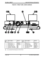
Figure 1: Front View ..................................................................................................... B-3
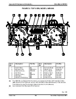
Figure 2: Top View ....................................................................................................... B-4
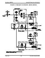
Figure 3: Pneumatic Schematic ................................................................................... B-5
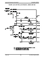
Figure 4A: Electrical Schematic
– MB1006 .................................................................. B-6
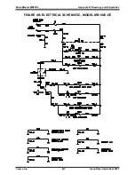
Figure 4B: Electrical Schematic
– MB1006-CE ............................................................ B-7
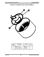
Figure 5: P/N MB1568 Tank Cover Assembly .............................................................. B-8
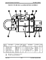
Figure 6: P/N MB1404-17 (-18) Abrasive Tank Assembly ............................................ B-9
Figure 7: P/N MB1290-7 (-8) Modulator Assembly ..................................................... B-10
Figure 8: P/N MB1083-3 Handpiece Assembly .......................................................... B-11
Figure 9: P/N MB1298-3 (-4) Abrasive Pinch Assembly ............................................. B-12
Figure 10: P/N MB1326-3 (-4) Air Pressure Regulator ............................................... B-13
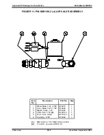
Figure 11: P/N MB1198-3 (-4) Air Valve Assembly .................................................... B-14
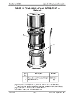
Figure 12: P/N MB1456-3 (-4) Tank Extender Kit ....................................................... B-15
Rev.12/11
Summary of Contents for MicroBlaster MB1006
Page 10: ......