background image

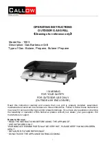
GAS-GRILL

Mod.

A

N

G

9.

G

INSTRUCTIONS FOR INSTALLATION, ADJUSTMENT, USE AND MAINTENANCE . . . . . . . . . . . . . . . . . . . . . . . . . . . . . . . . . . . . . . . . . . . . . . . . . . . . .page 2-4

APPENDIX . . . . . . . . . . . . . . . . . . . . . . . . . . . . . . . . . . . . . . . . . . . . . . . . . . . . . . . . . . . . . . . . . . . . . . . . . . . . . . . . . . . . . . . . . . . . . . . . . . . . . . . . . . . . . . .pagina 5-6

Read the manual thoroughly
and keep it in a safe place
throughout the product's
service life.

Read the warning notes
immediately!

DOC. NO.

CR0687740

0

805

Summary of Contents for ANG9.G

Page 1: ...IONS FOR INSTALLATION ADJUSTMENT USE AND MAINTENANCE page 2 4 APPENDIX pagina 5 6 Read the manual thoroughly and keep it in a safe place throughout the product s service life Read the warning notes immediately DOC NO CR0687740 0805 ...

Page 2: ...INSTALLATION DIAGRAM SERIE 90 Mod ANG9 G Measurements in cm Key G Attacco arrivo gas Gasanschluß Gas connection Arrivée Union de gasUNIISO 7 1 R3 4 CR0687740 1 ...

Page 3: ...1 JOINING APPLIANCES TOGHETHER IN LINE 2 ...

Page 4: ...FIG 2 MAIN BURNER PILOT BURNER FIG 3 GAS VALVE TAP 3 ...

Page 5: ...ATURAL GAS PROPANE NATURAL GAS PROPANE NATURAL GAS PROPANE 30 41 00 39 6 T1 INJIECTOR OREFICES SIZES MM A MM MARKING T2 BURNER AERATION SHUTTERS SETTING CR0687740 4 MM 18 MJ h 1 13 2 75 kPa T3 NOMINAL GAS CONSUMPTION T4 MAXIMUM GAS INLET PRESSURE 1 00 2 50 T5 NOMINAL TEST POINT PRESSURE VALUES VALUES SHOWN ARE THOSE MEASURED AT THE MANIFOLD PRESSURE TEST POINT kPa ...

Page 6: ...OCEDURE 5 Testing the gas system Testing the nominal thermal power Setting the manifold gas pressure TROUBLESHOOTING GUIDE 5 The pilot burner is difficult or impossible to ignite The pilot burner goes out during use The main burner is difficult or impossible to ignite REPLACEMENT OF SPARE PARTS 5 Burners Thermocouples Ignition electrodes Gas tap Piezo igniter USE AND MAINTENANCE INSTRUCTIONS 6 WAR...

Page 7: ...ferent gas supply follow the instructions below Use the injectors contained in the bag supplied with the appliance Replacement of burner injector and adjustment of burner air flow Fig 2 Remove the upper front panel and drawer Unscrew the existing injector U and replace it with the one indicated in Table T1 in Technical Data section Position the air regulator at the distance A indicated in Table T2...

Page 8: ...s While using the appliance empty them when they are nearly full For better cooking results and to facilitate cleaning at the end of the day pour 2 3 cm of water into each grease collection drawer Use of the grill The gas tap control knob has the following positions Ɣ Off Pilot ignition maximum cooking temperature minimum cooking temperature Turning on the burners Press the knob in and turn to the...

Reviews: