


Reflect-O-Ray
®
EDS-4DI & EHS-4DI
Installation, Operation & Service
Page 18
Combustion Research Corporation
GAS SUPPLY
In industrial installations where the natural gas pressure at
the meter is available at higher pressure than the standard
7" TO 14" W.C., it may be possible to cut down on gas
piping costs (when local codes and the Fire Marshal
approve) by running high pressure gas lines inside the
building or on the outside of the building. In no case should
the pressure exceed 10% of the service supply pressure.
When using a high pressure gas distribution system each
heating zone should be equipped with a pounds to inches
service regulator with soft seat, positive 100% lock-up.
Allowing high gas pressure on the downstream side of the
regulator will damage the control valve in the gas train. The
outlet pressure of the service regulators should be set at 7"
W.C. for natural gas and 11" W.C. for LP gases/propane
gases. If it is not practical to regulate in "zones", each
burner may be equipped with its own regulator.
To meet the requirements of 100% positive lock-up and
internal relief vent must be piped to the outside of the
building. It is recommended that an intermediate service
regulator, such as a Maxitrol 325 Series or approved equal
be used.
The typical discharge pressure on the down stream side of
the gas meter furnished by the gas company is usually 5
P.S.I.G. while the discharge pressure of the regulator on
the propane tank is usually set at 15 P.S.I.G.
Proper sizing of low and high pressure piping distribution
systems for natural gas should be made in accordance
with the National Fuel Gas Code, ANSI Z223.1 (current
standard) NFPA No. 54. Consult the supplier of the
propane tank and vaporizing system for the sizing of the
piping system for LP gas pipe work.
When leak testing the gas piping system, the Reflect-O-
Ray
®
burners must be isolated from the gas piping
system. High-pressure compressed air used in the leak
test will damage the control valve in the burner gas train,
which will result in unsafe operation of the burner(s). For
proper and safe test procedures, observe the provisions of
Part #4, of the National Fuel Gas Code, ANSI Z223.1
(current standard) -
Inspection, Testing and Purging
or
refer to equivalent local for the United States. In Canadian
see gas code CAN/CGA-B149.1& CAN/CGA-B149.2.
NOTE: It is important that the entire system, up to the
burner gas connection, be checked for leaks, prior to start
up.
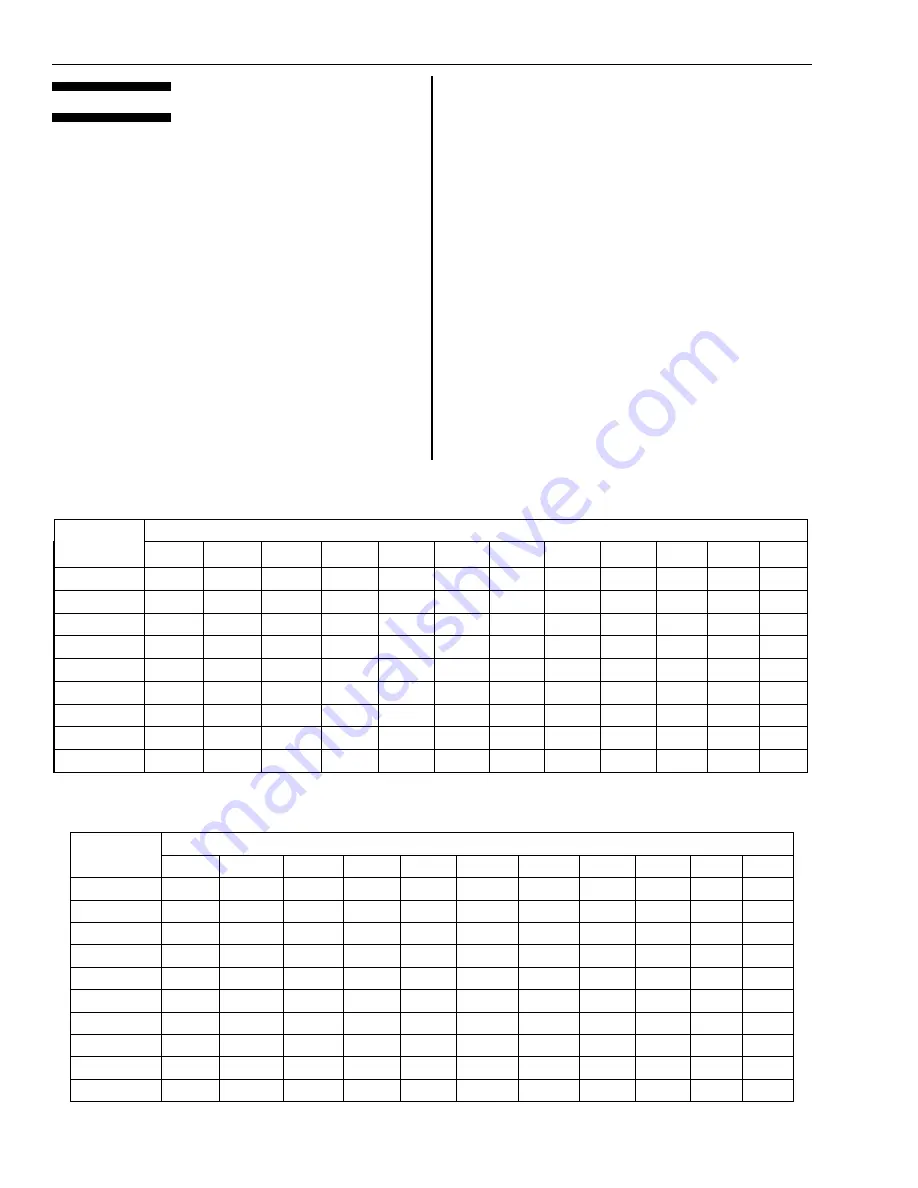
TABLE
MAXIMUM CAPACITY OF PIPE IN CUBIC FEET OF GAS PER HOUR
(Pressure Drop of 0.5 Inch Water Column and 0.6 Specific Gravity Natural Gas )
TOTAL EQUIVALENT LENGTH OF PIPE (FEET)
PIPE SIZE OF
STANDARD
SCH. 40 PIPE
10 20 30 40 50 75
100
125
150
175
200
250
1/2 120
85
70
60
54
44
38
34
31
29
27
24
3/4
272 193 157 136 115 99 82 76 67 65 58 52
1 545
385
315
272
244
198
173
154
141
130
122
109
1-1/4 1,201
848 693 600
537
439
380
340
310
287
268
240
1-1/2 1,862
1,316
1,074
931 832 680 588 527 480 445 416
372
2 3,766
2,663
2,174
1,884 1,680 1,373 1,190 1,065 971 900 841 753
2-1/2 6,165
4,358
3,559
3,082 2,752 2,254 1,950 1,743 1,593 1,473 1,379 1,233
3 10,502
7,426
6,063
5,250 5,015 3,841 3,549 3,106 2,895 2,682 2,508 2,242
4 22,031
15,577
12,718
11,015
10,510
8,158 7,430 6,548 6,060 5,066 5,250 4,700
TABLE
MAXIMUM CAPACITY OF PIPE IN CUBIC FEET OF GAS PER HOUR
(Available Pressure 5 P.S.I.G. 10% Pressure Drop and 0.6 Specific Gravity Natural Gas)
TOTAL EQUIVALENT LENGTH OF PIPE (FEET)
PIPE SIZE OF
STANDARD
SCH. 40 PIPE
50 100 150 200 250 300 400 500
1,000
1,500
2,000
1 1,863
1,320
1,074
931
832
760
658
584
416
341
293
1-1/4 3,880
2,744
2,240 1,938 1,732 1,580 1,370 1,218 866 708 609
1-1/2 5,860
4,140
3,375 2,920 2,620 2,384 2,065 1,835 1,310 1,070 918
2 11,360
8,060
6,560
5,680 5,080 4,640 4,025 3,570 2,540 2,080 1,792
2-1/2 18,280
12,933
10,540 9,140 8,180 7,460 6,460 5,740 4,090 3,390
2,875
3 32,620
23,100
18,800
16,300 14,500
13,310 11,520 10,250
7,290 5,960 5,125
4 67,400
47,600
38,840
33,650 30,160
27,550 23,800 21,140
15,080 12,330 10,620
5 122,900
86,900
71,000
61,400 55,000
50,200 43,450 38,600
27,500 22,570 19,400
6 201,000
142,700
115,000
100,300 89,800
82,100 71,800 63,000
44,900 36,700 31,590
8 418,000
295,000
240,800
208,500 186,800 170,800 148,000 131,200 93,400 73,400 65,600