


USER MANUAL FOR RX-2620
ENU STATUS : 1-0-0
Copyright - refer to title page
Page 20
3.4.6 CONNECTION BETWEEN PC AND EQUIPMENT
The below shows the connection:
Figure 8:
The Connection between Equipment and PC
Note that when connect the RJ45 Ethernet cable with PC, the equipment should be power off and Li-ion
battery output connector is disconnected.
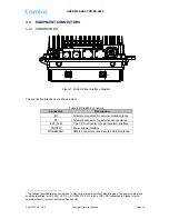
3.4.7 EXT ALARM CONNCETION
The EXT ALARM port is a 7-pin CPC connector. The following figure and table show the pin allocation
and definition. Pin numbering are shown looking-into the connector on the enclosure.
2
1
6
7
3
5
4
Figure 9: Pins Allocation for “EXT_ALM” Port
Table 5: Pin Definition of “EXT_ALM” Port
Pin
number
1
2
3
4
5
6
7
Alarm
definition
EXT.
Alarm 1
EXT.
Alarm 2
Reserved GND
Reserved Reserved Reserved
End of Section


