background image

USER MANUAL FOR COMFLEX-4500 5W


ENU STATUS : 1-0-0 

Copyright - refer to title page 

Page 32 


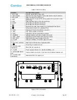
Table 5: MU Connections 


ANT

RX_EXT

TX_EXT

TEST

PWR
RUN

ALM

OP

DC 28V

LAN

RS-485

EXT_ALM

OP


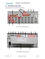
Figure 29: RU Connectors 

Identifier 

Functional Description 

1. OP1~OP4 

SC/APC optical fiber access port 

2. LED indicator 

LED indicator. See Chapter 4 for the description of each indicator. 

3. BTS_ALM 

DB9-F connector for BTS alarm. 

4. OMT 

RJ45 connector connects PC with equipment for local and remote 
monitoring. 

5. LAN 

Reserved RJ45 port for remote monitoring. 

6. TX/RX 

RF access port, Mini Din connector. 

7. RX 

RF access port, Mini Din connector. 

8. 


Digital display tube. See chapter 4 for the detailed description. 

9. 


Grounding connector for redundant PSU. 

10. FOU 

Expansion FOU communication connector 

11. POI 

POI  communication connector 

12. AUX 

Expansion unit communication connector 

13. MODEM 

Optional modem unit communication connector 

14. 28V+  GND 

Expansion FOU and RFU external power supply 

15. EXT_PSU 

Redundant PSU power supply connector 

16. LI_BAT 

Optional Li-Battery unit power supply connector 

17. / 


18. UL1,DL1; UL2,DL2 

Reserved for RF interface of extended FOU 

19. 


Grounding connector for rack 

20.  AC100~240V 
50Hz/60Hz 

Main PSU AC output port 

21. LI_BAT 

Power supply connector of  optional Li-Battery unit


22.  MODEM/MODEM       
ANT 

Communication connector /  Antenna port of optional moedem unit 

23.  AC100~240V 
50Hz/60Hz 

Redundant PSU AC output port 

Summary of Contents for MRU-4500

Page 1: ...M ME ED DI IU UM M PO OW WE ER R D DI IS ST TR RI IB BU UT TE ED D A AN NT TE EN NN NA A S SY YS ST TE EM M MRU 4500 USER MANUAL MRU 4500 5W QE 1 0 0 Comba Telecom Ltd...

Page 2: ...in which vests in Comba International Comba All rights reserved The information contained herein is confidential and the property of Comba and is supplied without liability for errors or omissions No...

Page 3: ...NG CONSIDERATIONS 17 3 3 INSTALLATION PROCEDURES 19 3 4 EQUIPMENT CONNECTORS 31 3 5 EQUIPMENT CONNECTION 34 4 COMMISSIONING 39 4 1 PRE COMMISSIONING TASKS 39 4 2 LED INDICATORS 39 4 3 DIGITAL DISPLAY...

Page 4: ...tion 29 Figure 24 Remote PSU installed on the right of RU 29 Figure 25 Mounting Rack Installation Unit inch 30 Figure 26 Remote PSU wall mounting 30 Figure 27 MU Front Panel Connectors 31 Figure 28 MU...

Page 5: ...59 Figure 74 Commissioning Procedure Params Setting 59 Figure 75 Dev Info Date Time 60 Figure 76 Flow to select 60 Figure 77 Calibration screen 61 Figure 78 Commissioning Procedure Automatic Calibrat...

Page 6: ...MFLEX 4500 5W ENU STATUS 1 0 0 Copyright refer to title page Page 6 0 3 HISTORY Change No ENU Details Of Change 1 1 0 0 This user manual first created in Oct 2014 which referred to its Chinese manual...

Page 7: ...rminal MTBF Mean Time Between Failures MU Master Unit NC Normally Closed NF Noise Figure NO Normally Open OMC Operation Maintenance Center OMT Operation Maintenance Terminal WebOMT Web Operation Maint...

Page 8: ...xt label may accompany the symbol label Hazard labeling is supplemented by safety notices in the appropriate equipment manual These notices contain additional information on the nature of the hazard a...

Page 9: ...he low signal transmission loss of optical fiber is applicable for long distance transmission ComFlex 4500 can support the optical transmission of up to 6 5dBo optical loss equivalent to 8 miles fiber...

Page 10: ...USER MANUAL FOR COMFLEX 4500 5W ENU STATUS 1 0 0 Copyright refer to title page Page 10 Figure 2 Remote Unit RU and RU PSU End of Section...

Page 11: ...The Optical TX RX Module of RU converts the DL optical signals into RF signals After amplification the signals are transmitted at the ANT port to the service antenna On the UL the signals transmitted...

Page 12: ...s optical signal and RF signal conversion One FOU has four optical ports which means each FOU can support up to four RUs MU01 RFU Master Unit RF Unit RFU completes separation and combination of uplink...

Page 13: ...the following part Table 2 RU Components Module Description MRU01 4500 Remote Unit A compact and slim design which supports 4 bands including 850MHz 1800MHz 2100MHz and 2600MHz bands LRU01 PSU A92W300...

Page 14: ...le 3 Master Unit MU KOP Item Qty Image MU Chassis 1 RF Unit RFU 1 8 Fiber Optical Unit FOU 1 2 FOU Dummy Load 0 1 RFU Dummy Load 0 6 Power Supply Unit PSU 1 Power Supply Cable 13 Feet 1 inch 1 Communi...

Page 15: ...1 Mounting Rack for RU wall mounting 1 Masonry Bolt set M8x80 for RU concrete wall mounting 4 Masonry Bolt set M8x80 for RU PSU concrete wall mounting 2 Nuts M10x25 Spring Washers 10 Plain Washers 10...

Page 16: ...t involving installation operation or maintenance must be free from danger as far as reasonably possible Where there is a risk of damage to electrical systems involving adverse weather extreme tempera...

Page 17: ...c sources such as large electrical equipment Environmental Humidity has an adverse effect on the reliability of the equipment It is recommended to install the equipment in locations having stable temp...

Page 18: ...thin reach of the power cord and the power source has sufficient capacity Where appropriate ensure unused RF connectors are terminated Where appropriate ensure unused optical fiber connectors are prot...

Page 19: ...items from packing materials until installation 3 3 2TOOLS See Appendix A for a full list of tools required for installation and maintenance 3 3 3PREPARATION Optical Fiber Fiber optic cables require p...

Page 20: ...mFlex Master Unit Step 1 RF Unit installation Remove RFU slot cover plate on Chassis insert RFU and fasten the screws Each Unit can be installed in any one of eight RFU slots Power Supply Unit Fiber O...

Page 21: ...tep 2 FOU installation Remove FOU slot cover plate on Chassis insert FOU and fasten the screws Each Unit can be installed in either one of two FOU slots Figure 8 FOU Installation Step 3 PSU installati...

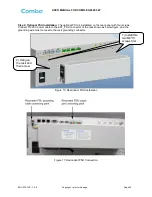
Page 22: ...stallated on the rear panel with four screws Connect DC 28V power cable to the EXT_PSU connector of the rack shown as below figure and the grounding wire must conncet to the rack grounding connector F...

Page 23: ...to the modem abutment before installation Access the optional modem unit into the slot on the rear panel and screw Connect MODEM connector with MODEM connector of the rack with communication cable in...

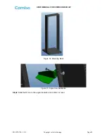
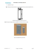
Page 24: ...ANUAL FOR COMFLEX 4500 5W ENU STATUS 1 0 0 Copyright refer to title page Page 24 Figure 14 Mounting Rack Figure 15 Angle Iron Installation Step2 Slide the MU on to the angle brackets and confirm it is...

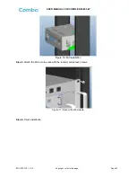
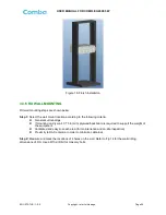
Page 25: ...FLEX 4500 5W ENU STATUS 1 0 0 Copyright refer to title page Page 25 Figure 16 MU Installation Step 3 Attach the MU onto the rack with the recommended rack screws Figure 17 Secure the Enclosure Step 4...

Page 26: ...he following criteria General surroundings If mounting on dry wall 0 75 In min plywood backboard is required to support the weight of the equipment Ventilated and easy to reach area for maintenance an...

Page 27: ...Wall Drilling Dimensions of RU Unit inch Step 3 Attach the mounting rack on a wall If a concrete wal use the 4 M10 110 masonry bolts Two M8x80 Masonry bolts Figure 20 Install Mounting Rack on the Wal...

Page 28: ...Figure 21 Hang RU onto the Mounting Rack Step 5 Tighten the RU on masonry bolts with four M8 80 nuts Figure 22 Tighten the Screws at the Bottom of RU Step 6 Check the RU installated tightly and the he...

Page 29: ...7 Remote PSU Installation Remote PSU should be installed afer RU finish installation It can be installed on the RU or on the wall nearby RU Installed on RU Remote PSU should be installed on the right...

Page 30: ...0 Installed on the wall Step 1 Measure and mark two holes on the wall nearby RU the max demision from RU is 0 5m 14 96 4 37 Figure 25 Mounting Rack Installation Unit inch Step 2 Screw two hexagonal ma...

Page 31: ...Copyright refer to title page Page 31 3 4 EQUIPMENT CONNECTORS The figures below present the connectors of ComFlex MU 1 2 3 4 5 6 7 8 Figure 27 MU Front Panel Connectors 13 12 11 10 9 14 15 16 17 18 1...

Page 32: ...n connector 8 Digital display tube See chapter 4 for the detailed description 9 Grounding connector for redundant PSU 10 FOU Expansion FOU communication connector 11 POI POI communication connector 12...

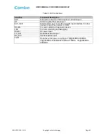
Page 33: ...cal fiber access port EXT_ALM External alarm port It provides an alarm report interface for other devices to report their alarms to CMS RS 485 For communication of expansion device LAN For local monit...

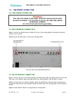
Page 34: ...ied copper wire GND cable to RU Grounding point and connect the other side of the supplied copper wire GND cable to the building EARTH with two M6 10 screws Step 2 Connect one side of another supplied...

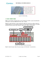
Page 35: ...plex application connect the MU RFU TX RX port to the RF Source BTS or BDA For simplex application connect the MU RFU TX RX port to the RF Source downlink and then connect MU RFU RX port with RF Sourc...

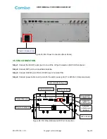
Page 36: ...a broadband antenna Step 3 Connect DC28V port of RU to DC28V port of remote PSU Step 4 Connect power cable on AC port with the public power grid 110 220VAC 6Amp maximum ANT PWR RUN ALM OP OP EXT_ALM R...

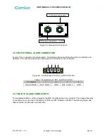
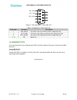
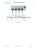
Page 37: ...and definition Pin numbering are shown looking into the connector on the enclosure 1 2 3 4 Figure 36 Pins Allocation for EXT_ALM Port for RU Table 7 Pin Definition of EXT_ALM Port for RU Pin number 1...

Page 38: ...the open terminal of the voltage free relay 2 BTS_COM Connects to the common terminal of the voltage free relay 3 BTS_CLOSE Connects to the close terminal of the voltage free relay 4 9 NC Reserved 3 5...

Page 39: ...anel and RU bottorm panel each indicates the status of a particular function Table 9 MU LED Indications LED Indicator Normal Status Indication PWR Steady green Power indicator If LED is off it indicat...

Page 40: ...ll show L when DL input powe is higher than 33 it will display H Figure 38 RFU Digital Display Table 11 RFU Digital Display Figure DL Input Power Level L 19dBm 19 33 19 33dBm H 33dBm 4 3 2 DIGITAL DIS...

Page 41: ...FOR COMFLEX 4500 5W ENU STATUS 1 0 0 Copyright refer to title page Page 41 A b C d Figure 39 Optical Port No and Digital Display Table 12 FOU Digital Display Figure Optical Loss 0 9 0 9dBo H 9dBo End...

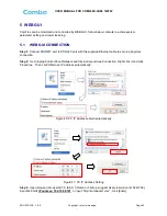
Page 42: ...45 port with the supplied Ethernet cable to set up a physical connection Step 2 Go to laptop Control Panel Network and Internet Local Area Connection Right click it and click Properties Then click Obt...

Page 43: ...R COMFLEX 5H00 1W2W ENU STATUS 1 0 0 Copyright refer to title page Page 43 Figure 42 Input IP Address Step 4 Input User Name admin Password default password admin Click Log in Figure 43 Input User Nam...

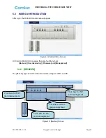
Page 44: ...GUI Main Screen On Comba Web GUI Home page there are four Menu bars Devices Commissioning Firmware and Management 5 2 1 DEVICES The Devices page shows the actual connection diagram of MU and RU Figure...

Page 45: ...Page 45 MU Main Management Screen Figure 46 MU Device Monitoring Unit Optical Unit Management Screen Figure 47 MU Device Optical Unit Note MU transmit optical power is 4 2dBm This part shows MU basic...

Page 46: ...re connected by optical fiber RU device scanning is done Note Go to Commissioning page or Management page for device scanning Figure 49 RU Device NOTE There are three statuses for PA Service Normal Re...

Page 47: ...ix times of PA Recovery PA Service status will be Shutdown which will need to be reset manually Reset at Management PA Reset Click on a specific band on the left side of RU Device page the correspondi...

Page 48: ...sed to upgrade software and Swap is to replace current firmware version to the previous one Follow steps shown in below figure to upgrade firmware Figure 52 Firmware Screen Upgade Step 4 After clickin...

Page 49: ...g reset Figure 54 Firmware Screen Pop up Window 2 Step 6 Clear browsing history and cookies from browser NOTE For MU software upgrade users need to re login Web GUI after reset is done Follow steps sh...

Page 50: ...e 50 Figure 56 Firmware Screen Module upgrade 5 2 4 MANAGEMENT Other parameters can be configured on Management page Figure 57 Management Screen Click here to enter corresponding page Select device pa...

Page 51: ...aremeter Device Parameter MU Alarm Enable RU Alarm Enable ATT value ATT value RF Switch RF Switch SNMP parameter Over temperature alarm threshold DL over output power threshold External Alarm level Im...

Page 52: ...1 0 0 Copyright refer to title page Page 52 IP Setting Figure 59 Management IP Setting Note Here the device IP Address CANNOT be set as 192 168 8 SMS Setting Figure 60 Management SMS Setting Configur...

Page 53: ...NUAL FOR COMFLEX 5H00 1W2W ENU STATUS 1 0 0 Copyright refer to title page Page 53 Maintenance Figure 61 Management Maintenance Security Figure 62 Management Security Click Modify Password window will...

Page 54: ...e 63 Modify Password Note Username cannot be modified Device Reset Figure 64 Management Device Reset Note Device Reset process will last about 2 4 minutes For MU monitor reset users need to re login W...

Page 55: ...PA will be turned off by software when PA output power or VSWR reflected power is exceed the threshold Users need to reset PA after debugging Device Info Figure 66 Management Device Info Note Users c...

Page 56: ...1 of Commissioning Running scanning software will allocate an ID to RU so that MU can identify and visit it Device Remove Figure 68 Management Device Remove Note If the RU has been scanned and identif...

Page 57: ...ER MANUAL FOR COMFLEX 5H00 1W2W ENU STATUS 1 0 0 Copyright refer to title page Page 57 Report Figure 69 Management Report License Figure 70 Management License Device frequency band authorization statu...

Page 58: ...ement Alarm Log 5 3 COMMISSIONING PROCEDURE To complete the installation and commissioning users need to follow the steps below Step 1 Click Menu bar Commissioning on home page a work flow will show u...

Page 59: ...1 0 0 Copyright refer to title page Page 59 Figure 73 Commissioning Procedure Device Scan Step 3 Click to enter to Params Setting page Click users can set the device information and system time Figur...

Page 60: ...r time Step 4 Click to enter to the page to select folw to continue There are three flows to select Goto calibration flow Goto setup flow and Finish flow Figure 76 Flow to select NOTE1 Calibration is...

Page 61: ...m before proceeding to step 5 Step 5 Select Goto calibration flow and click to enter to Calibratiion page after finishing Parems Setting Figure 77 Calibration screen Automatic calibration no need to s...

Page 62: ...OMFLEX 5H00 1W2W ENU STATUS 1 0 0 Copyright refer to title page Page 62 Figure 78 Commissioning Procedure Automatic Calibration Figure 79 Commissioning Procedure Manual Calibration Select RU and frequ...

Page 63: ...1 0 0 Copyright refer to title page Page 63 Figure 80 Commissioning Procedure Calibration Finish Step 6 Click to enter to MU Setup page after finishing Calibration Figure 81 Commissioning Procedure MU...

Page 64: ...U unit RF Switch Set the RF switch status of this RF unit DL Input Power Input Power of the BTS signal access to this RF unit Note ComFlex system reaches its rated output power 30dBm when input power...

Page 65: ...U Figure 84 RU Frequency Band Table Two parameters need to be set in this step RF Switch Set the RF switch status of Remote Unit Target DL Output Power Expected DL output power setting Note Rated outp...

Page 66: ...and they have the same input power level each channel will reach it s rated power so the total output power will be input A gain inputB gain inputN gain For example if there are two 1900MHz bands ace...

Page 67: ...e the same H L level with alarm level otherwise normal Alarm period 10s by default Over Temperature Alarm Alarm when equipment temperature is higher than the threshold otherwise normal Alarm judgment...

Page 68: ...alarm Check device temperature on WEB GUI If device temperature e is over threshold make sure environment temperature is within the envireonment temperature range that RU supported 20 50 Apply climat...

Page 69: ...1 APPENDIX A TOOLS FOR INSTALLATION AND MAINTENANCE The following tools not included in package are required for installation or routine maintenance Power Drill for wall mount Adjustable Wrench 0 31 i...

Page 70: ...USER MANUAL FOR COMFLEX 5H00 1W2W ENU STATUS 1 0 0 Copyright refer to title page Page 70 7 2 APPENDIX B RMA RETURN MATERIAL AUTHORIZATION End of Section End of Document...

Page 71: ...USER MANUAL FOR COMFLEX 5H00 1W2W ENU STATUS 1 0 0 Copyright refer to title page Page 71...

Reviews: