background image

INSTALLATION GUIDE FOR SR-1910 


SR-1910 QI 

Copyright - refer to title page 

Page 27

ENU Status : 1-1-1 


3.6 PREPARATION FOR REMOTE CONTROL OF EQUIPMENT USING 
WIRELESS MODEM 

Wireless Modem 

 
For the equipment variant equipped with wireless modem, the modem provides the option of remote 
connection of the equipment via the OMT. The wireless (GSM) modem implements the link for data and 
SMS functions.  
 
Note: When CDMA modem is used, only SMS function is supported to retrieve alarm information and to 
provide remote control. 
 
The power and data cables have been factory-connected to the wireless modem. User only needs to insert 
the SIM / UIM card to the GSM / CDMA modem. 
 
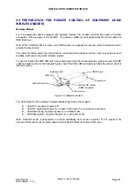
To insert or replace the SIM /UIM card, locate and press down the recessed button (yellow) to eject the SIM 
/ UIM card carrier (refer to the following figure). Insert the SIM / UIM card and push back the carrier until it is 
latched in place. 
 

SIM card

SIM card carrier

Yellow button

Indicator LED

Modem RF output

(SMA connector)

RS232 port

Power port

SIM card

SIM card carrier

Yellow button

Indicator LED

Modem RF output

(SMA connector)

RS232 port

Power port


Figure 12: Wireless modem 


The LED indicator of the wireless modem displays the state of the modem: 
 

z


LED OFF: equipment power off 

z


LED ON: equipment power on, no SIM / UIM card or no connection to antenna 

z


LED flash slowly: equipment power on, in SMS mode 

z


LED flash quickly: equipment power on, in data link mode 

 
Note: Data link mode is dependent on service availability from service operator. If it is required, the 
operator’s SIM card must be data-enabled (Circuit Switch Data) and without PIN code. 


Summary of Contents for GSM1900

Page 1: ...AND ADJUSTABLE REPEATER INSTALLATION GUIDE This is an unpublished work the copyright in which vests in Comba International Comba All rights reserved The information contained herein is confidential an...

Page 2: ...INWARDS INSPECTION 21 3 3 2 TOOLS 21 3 3 3 MOUNTING ARRANGEMENT 21 3 3 4 WALL MOUNTING DETAILS 22 3 3 5 DRIP LOOP 22 3 4 EQUIPMENT CONNECTORS 23 3 5 EQUIPMENT CONNECTIONS 24 3 5 1 GROUNDING CONNECTION...

Page 3: ...10 QI Copyright refer to title page Page 3 ENU Status 1 1 1 4 6 1 ALARM ACKNOWLEDGEMENT 36 4 7 COMMISSIONING PROCEDURES 37 5 MAINTENANCE 38 6 APPENDICES 39 6 1 APPENDIX A TOOLS 39 6 2 APPENDIX B RMA R...

Page 4: ...port 25 Figure 10 Pin allocation and definition of the RS 485 port 25 Figure 11 Pins allocation for 7 pin EXT_ALM connector for external alarms 26 Figure 12 Wireless modem 27 Figure 13 Diagram of wir...

Page 5: ...5 ENU Status 1 1 1 0 4 HISTORY Change No ENU Details Of Change 1 1 0 0 First developed and issued in April 2007 2 1 1 0 Document is restructured sections of KOP and Maintenance deleted description on...

Page 6: ...INSTALLATION GUIDE FOR SR 1910 SR 1910 QI Copyright refer to title page Page 6 ENU Status 1 1 1 0 5 ISSUE CONTROL Date 13 Sep 06 14 Jun 07 Section All All All...

Page 7: ...NU Status 1 1 1 0 6 REFERENCES 0 6 1 SR 1910 C1 C2 SR 1910 1001YH SR 1910 GSM900 Indoor Band Adjustable Repeater Original Manual released in August 2006 0 6 2 SR 1910 DS 2 2 2 Datasheet released on 26...

Page 8: ...lifier GSM Global Standard for Mobile Communication Hz Hertz ID Identification IF Intermediate Frequency LNA Low Noise Amplifier LOS Line of Sight MCU Main Control Unit MHz Megahertz MT Mobile Termina...

Page 9: ...e text label may accompany the symbol label Hazard labelling is supplemented by safety notices in the appropriate equipment manual These notices contain additional information on the nature of the haz...

Page 10: ...Address 611 East Wing No 8 Science Park West Avenue Hong Kong Science Park Hong Kong Tel 852 2636 6861 Fax 852 2637 0966 Email combahk comba telecom com Singapore Office Address 865 Mountbatten Road...

Page 11: ...that any amendment remedial action can be carried out promptly it is necessary to fill out and return a photocopy of this customer reply sheet as soon as possible Customer Information Name Title Compa...

Page 12: ...table from 15M to 60M and customized 15M fixed bandwidth z Adjustable centre frequency within 60M of the 1900MHz frequency band z Superior filtering and amplification designed for both uplink and down...

Page 13: ...R SR 1910 SR 1910 QI Copyright refer to title page Page 13 ENU Status 1 1 1 The following figure shows the enclosure of the SR 1910 152 430 300 Figure 1 Front side and bottom views of the SR 1910 encl...

Page 14: ...a of the repeater After the duplexer the signals are sent to the LNA for pre amplification followed by band filtering through the Frequency Selection FS Module The power amplifier PA will then amplify...

Page 15: ...egrated wireless modem The Master Unit is locally connected with the Slave Unit via RS 485 communication bus The communication between the Master Unit and OMT OMC is via SMS or datalink Figure 3 Centr...

Page 16: ...refer to title page Page 16 ENU Status 1 1 1 2 3 EQUIPMENT LAYOUT Shown below is the internal layout of the SR 1910 Integrated UL Duplexer Integrated DL Duplexer PSU RF Integrated Module MCU Li ion Ba...

Page 17: ...fier Module PA With the ATT and ALC functions it fulfils power amplification in both UL and DL branches Distribution Board It provides connectivity to the functional modules and connection between the...

Page 18: ...ditions flammable or explosive atmospheres the system must be suitably installed to prevent danger Protective Earthing Equipment provided for the purpose of protecting individuals from electrical risk...

Page 19: ...signed to operate at the temperature range and humidity level as stated in the product specifications in the datasheet Direct sun light exposure to the equipment should be avoided Provide additional s...

Page 20: ...in feeder cable by minimizing the length and number of RF connections Ensure VSWR of antennas system 1 5 1 Ensure equipment will be operated within the stated environment see datasheet Where needed c...

Page 21: ...e during transit is the responsibility of the agent z Open and check each package against the packing list If any items are missing contact Comba z Do not remove items from anti static packing until r...

Page 22: ...Hook the enclosure onto the masonry bolts and then lower the whole enclosure to make sure that the bolts are fastened into the narrow slots of the mounting tabs Tighten nuts to secure the masonry bolt...

Page 23: ...onnection to donor antenna MT N Female connector for connection to service antenna RS 232 5 pin round connector for local commissioning with the supplied commissioning cable RS 485 5 pin round connect...

Page 24: ...roduct accepts AC 220 or AC 110V power depending on the type of PSU installed The equipment accepts single phase 220VAC 110VAC power The recommended AC connection is rated at AC220V 3 15A and has thre...

Page 25: ...NIT When Slave Units are included in a centralized control and monitoring System physical connection between Master Unit and Slave Unit must be established prior to the commissioning This is establish...

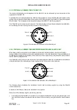
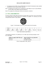
Page 26: ...1910 are provided on the EXT_ALM port which is a 7 pin round connector The following figure and table shows the pin allocation and definition Pin numbering are shown looking into the connector on the...

Page 27: ...te and press down the recessed button yellow to eject the SIM UIM card carrier refer to the following figure Insert the SIM UIM card and push back the carrier until it is latched in place SIM card SIM...

Page 28: ...nal RS232 Port It is a DB9 port which connects to the DB9 port on the distribution board VDC Input Connects to 10 30 VDC supply Table 5 Wireline modem connectors On the modem there are five status LED...

Page 29: ...nclosure bottom Refer to detailed LEDs information in the next section 4 2 EQUIPMENT LED INDICATORS Three diagnostic LED indicators are located on the bottom of the enclosure Each LED indicates the st...

Page 30: ...system and is designed for monitoring and maintaining of Comba repeaters and boosters For SR 1910 repeater the OMT software can accomplish the following functions To configure and adjust the repeater...

Page 31: ...ower loss Repeater Network Configuration Device ID SMS report mode including SMS center number and OMC report number setting Datalink report mode Operating Parameters Pre ATT Power Supply Switch Outpu...

Page 32: ...information which will be displayed on the right side of the OMT screen in which the equipment model name equipment site ID and site sub ID will be shown Figure 15 System information window Clicking...

Page 33: ...lue should be within the Downlink Input Overload Threshold and Downlink Output Power Low Threshold respectively Otherwise a DL Input Overload Alarm or DL Output Power Low Alarm will be generated A mea...

Page 34: ...ight interface of the OMT screen Up to four external devices can be connected to the SR 1910 via the EXT_ALM connector on the enclosure by doing that the working status of external devices can be moni...

Page 35: ...tered by the user after successful connection to the equipment The Checking Control parameter group includes only one parameter Enable Phone No Checking Phone Number Authentication feature is enabled...

Page 36: ...er Fault alarm Check AC power cable and verify AC mains supply is normal During power fault alarm DC power supply has no output Check if DC output power is overloaded or short circuited The PSU could...

Page 37: ...input power and align donor antenna Select RF Parameters and observe the DT port received signal level Align the donor antenna to maximize the DL input power reading 3 Check DL output power Set the DL...

Page 38: ...Ensure the reliable connection of cables power cords and facilities located indoor Inspect and record operation status and parameters such as receive signal level output noise level DL output power o...

Page 39: ...following are the recommended list of tools for new installation and routine maintenance Slotted Screwdriver Philips Screwdriver Ring Spanner Assorted size 12 20mm Electrically operated drill and maso...

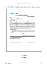
Page 40: ...INSTALLATION GUIDE FOR SR 1910 SR 1910 QI Copyright refer to title page Page 40 ENU Status 1 1 1 6 2 APPENDIX B RMA RETURN MATERIAL AUTHORIZATION FORM End of section End of Document...

Reviews: