Comax AB105R Installation Manual Download Page 1

I

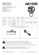
nstallation/Anschluss

Installation/Raccordement

Installation/Connection


0.4Nm


5mm

0.5   2.5mm 

• 

Sounder unit: Alarm horn sounder: 64 tones, 4 stages 

• 

Rotating Beacon: 20W/25W Halogen

• 

IP Rating: IP65

• 

Temp: -40̊ to + 66̊ 

• 

Unit weight: 1.15kg DC 1.30kg AC

• 

CE & UKCA

• 

2-off M20 x 1.5 thread entries.

Attention

: Installation must be carried out by an electrician in compliance with the latest codes and regulations. 

Attention

: L'installation doit être effectuée par un électricien conformément aux derniers codes et réglementations.  

Achtung

: Die Installation muss von einem Elektriker gemäß den neuesten Vorschriften und Bestimmungen durchgeführt werden. 

Attention

: Disconnect from power source before installation or service to prevent electric shock  

Attention

: Débranchez-le de la source d'alimentation avant l'installation ou l'entretien pour éviter tout choc électrique. 

Achtung

: Vor Installation oder Wartung von der Stromquelle trennen, um einen Stromschlag zu vermeiden. 

AC: 1.0 – 2.5mm

/ AWG18 – AWG12 

DC: 0.2 – 2.5mm

/ AWG24 – AWG12 

Unit Type Code 

Nominal 

Voltage 

Voltage Range 

Nominal 

Sounder 

Current 

Nominal 

Beacon 
Current 

Nominal SPL  

Max SPL 

Average SPL 

AB105

R.

012

.2

12VDC

10-15Vdc 20W

17mA

1720mA

105.3dB(A) 

Tone 44 @ 1m 

110.9dB(A) 

Tone 4 @ 1m 

105.2dB(A) All 

tones @1m  

AB105

R.

024

.2

24VDC

18-30Vdc 20W

33.5mA

910mA

AB105

R.

115

.7

115VAC

103.5-126.5Vac 

50/60Hz 25W

25mA

216mA

AB105

R.

230

.7

230VAC

207-253Vac

50/60Hz 25W

17mA

117mA

Supply voltage variation of +/-10% outside the voltage range is permissible 

Nominal current at nominal voltage 

A

B

10

5

R

Comax Industrielle Signaltechnik,

 CH-4712 Laupersdorf

www.comax.ch

Installationsanleitung_A

B

10

5

R

_REV2_

23

_0

7

_2021

Summary of Contents for AB105R

Page 1: ...electric shock Attention D branchez le de la source d alimentation avant l installation ou l entretien pour viter tout choc lectrique Achtung Vor Installation oder Wartung von der Stromquelle trennen...

Page 2: ...UAL AB105R Default S2 Tone 1 Default S1 Tone 44 ON 1 OFF 0 AC DC See D221 95 001 N L DC See D118 06 001 AC See 118 06 001 S2 S3 S2 S1 S2 S1 N L E E S3 S2 N L Note Beacon pre wired as default Note Beac...

Page 3: ...screw clockwise remove the existing lens by rotat ing the lens to align with the unlock markings as shown below Replace the lens cover and rotate to the locked marking position Rotate the 1 off M4 po...

Page 4: ...INSTRUCTION SERVICE MANUAL AB105R 4x 1Nm 20mm If a high IP Ingress Protection rating is required then a suitable sealing washer must be fitted under the cable glands or blanking plugs...

Page 5: ...1 0 1 0 0 1 1 0 1 0 0 0 0 1 1 0 0 1 0 1 1 0 0 0 1 1 1 0 0 1 1 1 1 0 0 0 0 0 0 1 0 1 0 0 0 1 0 0 1 0 0 1 0 1 1 0 0 1 0 0 0 1 0 1 0 1 0 1 0 1 0 0 1 1 0 1 0 1 1 1 0 1 0 1 1 0 1 1 0 0 0 1 1 1 0 0 1 1 1 1...

Page 6: ...on Config 1a Line Monitoring Stage 1 Apply Power to Stage 1 ve Stage 1 ve Two Stage Configuration Config 1b Common Positive Stage 1 Apply Power to Common ve Stage 1 ve Stage 2 Apply Power to Common ve...

Page 7: ...age 1 ve Stage 1 ve Two Stage Configuration Config 2b Common Positive Stage 1 Apply Power to Common ve Stage 1 ve Stage 2 Apply Power to Common ve Stage 1 ve connect Stage 2 ve to Stage 1 ve Three Fou...

Page 8: ...9 G F E 7 8 6 5 D C 1 3 4 2 A B OF NTS 3 SWITCHES FOR STAGE OPERATION CUSTOMER SUPPLIED WIRING LINKING BEACON SOUNDER FACTORY FITTED 4 Single Stage Configuration Config 3a Stage 1 Apply Power to Stage...

Page 9: ...B C D E F G 10 9 G F E 7 8 6 5 D C 1 3 4 2 A B R N POTTS OF NTS 4 SWITCHES FOR STAGE OPERATION CUSTOMER SUPPLIED 4 Single Stage Configuration Config 4a Stage 1 Apply Power to Stage 1 Live Stage 1 Neu...

Reviews: