INSTRUCTION & SERVICE MANUAL
A105
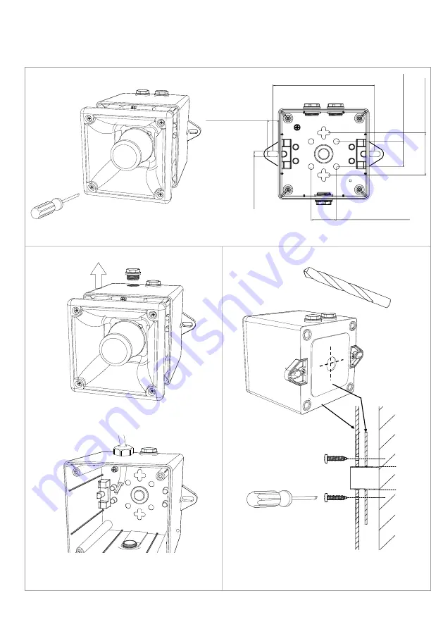
4x
1Nm
<
ø
20mm
145 5,71in.
60
,3
2,
37
in
.
35
,9
2
1
,4
1in
35,92 1,41in.
16,72 0,66in.
7,
72
0,
30
Page 1: ...durchgef hrt werden Attention Disconnect from power source before installation or service to prevent electric shock Attention D branchez le de la source d alimentation avant l installation ou l entret...
Page 2: ...S2 S3 S2 S1 S2 S1 E E S3 S2 N L Default S2 Tone 1 Default S1 Tone 44 ON 1 OFF 0 AC DC See D221 95 001 DC AC See D218 06 001 See D218 06 005...
Page 3: ...INSTRUCTION SERVICE MANUAL A105 4x 1Nm 20mm 145 5 71in 60 3 2 37in 35 92 1 41in 35 92 1 41in 16 72 0 66in 7 72 0 30in...
Page 4: ...Current 125mA 60Vdc DP 2821 CPR 0107 A105 024 2 1m Horizontal Sound Output Max Voltage 60 Vdc LAFmax T dB A Horizontal Sound Output Min Voltage 18 Vdc LAFmax T dB A Angle Tone 44 Tone 8 Tone 2 Tone 21...
Page 5: ...e installation on ships in the following locations Temperature A B C D Machinery spaces control rooms accommodation bridge inside cubicles desks etc pump rooms holds rooms with no heating Open deck ma...
Page 6: ...1 0 1 0 0 1 1 0 1 0 0 0 0 1 1 0 0 1 0 1 1 0 0 0 1 1 1 0 0 1 1 1 1 0 0 0 0 0 0 1 0 1 0 0 0 1 0 0 1 0 0 1 0 1 1 0 0 1 0 0 0 1 0 1 0 1 0 1 0 1 0 0 1 1 0 1 0 1 1 1 0 1 0 1 1 0 1 1 0 0 0 1 1 1 0 0 1 1 1 1...
Page 7: ...electric shock D branchez le de la source d alimentation avant l instal lation ou l entretien pour viter tout choc lectrique Attention Do not paint Ne pas Peinturer 40 C to 66 C 40 F to 151 F Units c...
Page 8: ...TS 1 1 OPTIONAL LINE MONITORING RESISTOR CUSTOMER SUPPLIED 14V MAX SYSTEM 120 MIN 2W MIN OR 1K MIN 0 5W MIN 28V MAX SYSTEM 470 MIN 2W MIN OR 2 4K MIN 0 5W MIN RECOMMENDED MINIMUM VALUES R1 Single Stag...
Page 9: ...M DRAWING NUMBER A B C D E F G 10 9 G F E 7 8 6 5 D C 1 3 4 2 A B D218 06 005 R S RAIT B ISARD R N POTTS OF A100 A105N D105 AC WIRING DIAGRAMS NTS 1 SWITCHES FOR STAGE OPERATION CUSTOMER SUPPLIED 1 Si...
Page 10: ......
Page 11: ......
Page 12: ......