background image

InteliVision 13Touch Global Guide

11

3.2 Rear panel description

3.2.1 Rear panel

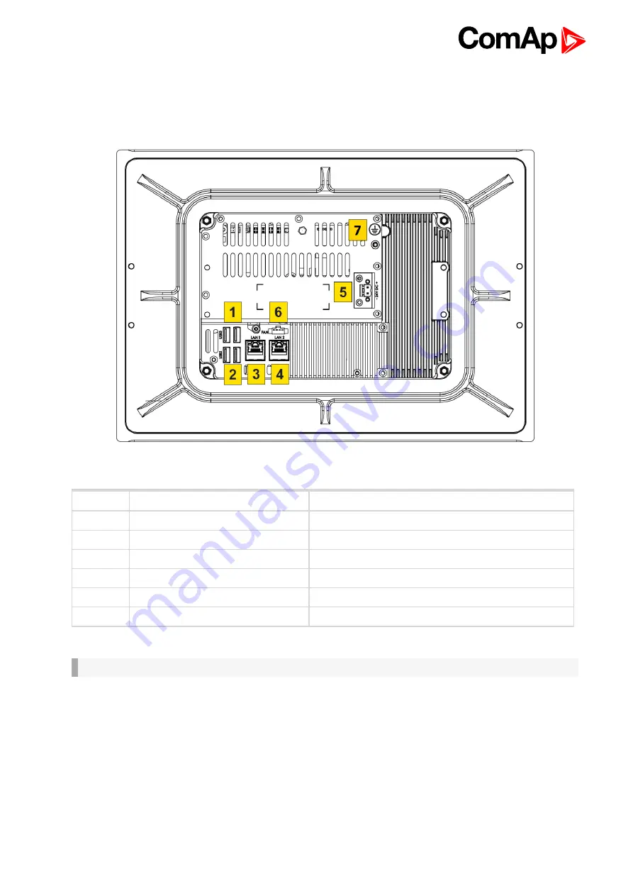
Image 3.2 Rear bottom panel description

Number

Title

Description

1

USB 3.0 Type A (Host)

2 x 9-pin USB Type A

2

USB 2.0 Type A (Host)

2 x 4-pin USB Type A

3,4

Ethernet RJ45

2 x 8-pin RJ45 10/100/1000Mbps LAN/Ethernet

5

DC Power Input

1 x 2-pin Termin Block 5.08 - DC Power Input

6

External Fan Connector

Not used.

7

Earthing

Earthing screw connector.

IMPORTANT: It is strictly recommended to use earthing in any circumstances.

Summary of Contents for InteliVision 13Touch

Page 1: ...ap control com www comap control com Global Guide InteliVision 13Touch 13 3 display unit for ComAp controllers SW version 1 0 1 Document information 4 2 System overview 8 3 Installation and wiring 10 4 Display Unit Settings 15 5 InteliVision 13Touch connection possibilities 16 6 Automatic SCADA start and connecting to the system 22 7 Creating a SCADA diagram 23 ...

Page 2: ...et LAN Ports 14 3 6 1 LAN Ports 14 4 Display Unit Settings 15 4 1 Touchscreen settings 15 4 2 On Screen Keyboard OSK settings 15 5 InteliVision 13Touch connection possibilities 16 5 1 InteliVision 13Touch connection to a Single gen set 16 5 1 1 Ethernet direct connection 16 5 1 2 USB connection 17 5 2 InteliVision 13Touch connection to a Multiple gen set 18 5 2 1 Multiple Ethernet Connection 18 5 ...

Page 3: ...InteliVision 13Touch Global Guide 3 7 2 2 Creating SCADA on another PC 26 ...

Page 4: ...part of ComAp s Product and may be used exclusively according to the conditions defined in the END USER or Distributor LICENSE AGREEMENT CONDITIONS COMAP CONTROL SYSTEMS SOFTWARE License Agreement and or in the ComAp a s Global terms and conditions for sale of Products and provision of Services Terms and or in the Standardní podmínky projektů komplexního řešení ke smlouvě o dílo Standard Condition...

Page 5: ...owever ComAp is prepared to provide technical support to resolve problems arising from such actions including but not limited to restoring settings prior to the cyber attacks backing up data recommending other preventive measures against any further attacks Warning Some forms of technical support may be provided against payment There is no legal or factual entitlement for technical services provid...

Page 6: ...B Class A This equipment has been tested and found to comply with the limits for a Class A digital device pursuant to part 15 of the FCC Rules These limits are designed to provide reasonable protection against harmful interference when the equipment is operated in a commercial environment This equipment generates uses and can radiate radio frequency energy and if not installed and used in accordan...

Page 7: ...l Gen set Controller IG NT GC InteliSysNTC Hybrid Hybrid system controller IS NTC HYBRID InteliMainsNT Mains Supervision Controller IM NT GC InteliDrive DCU Marine Modular Certified Engine Controller for Marine Applications ID DCU MARINE InteliGenNTBaseBox Complex Parallel Gen set Controller with Detachable Colour Display IG NT BB InteliLiteNT Manual Remote Start MRS Gen set Controller IL NT MRS15...

Page 8: ...ADA software enabling users to freely configure their screen with different types of items such as meters bar graphs numeric values control buttons pictures etc The software allows users to check the history of multiple controllers and change setpoints from a single location IGS LOG software is also preinstalled at no extra cost for continuous logging of desired parameters InteliVision 13Touch is ...

Page 9: ...wn left right typical Backlight LED Type P Cap Projected Capacitive Touch Touchscreen Housing IP66 front IP20 rear EN60529 Weight approx 3 0 kg 6 6 lbs Dimensions W H D 355 00 13 98 248 50 9 78 69 00 2 72 mm inch Mechanical OS Windows 10 IoT Enterprise 2019 LTSC 64bit Operating system ...

Page 10: ...11 3 3 Dimensions drawings 12 3 4 Mounting 12 3 5 Power 13 3 6 Ethernet LAN Ports 14 6 back to Table of contents 3 1 Front panel description Image 3 1 Front panel overview Title Description LED indication Status RGB LED Brightness settings Brightness setting using buttons plus minus Power ON OFF Power ON OFF of the device ...

Page 11: ...USB 3 0 Type A Host 2 x 9 pin USB Type A 2 USB 2 0 Type A Host 2 x 4 pin USB Type A 3 4 Ethernet RJ45 2 x 8 pin RJ45 10 100 1000Mbps LAN Ethernet 5 DC Power Input 1 x 2 pin Termin Block 5 08 DC Power Input 6 External Fan Connector Not used 7 Earthing Earthing screw connector IMPORTANT It is strictly recommended to use earthing in any circumstances ...

Page 12: ...Vision 13Touch is designed to mount on a panel InteliVision 13Touch has an external bracket mounting system Clips are included in the package The recommended cutout size for panel mounting is 343 00 mm width x 236 50 mm height Insert InteliVision 13Touch into the cut area and from the rear side install the attached mounting clips and fix them with a screwdriver ...

Page 13: ...stallation of the front frame sealing is a must to fulfill IP66 protection standard IMPORTANT Do not overtighten the screws to prevent damaging the Panel PC IMPORTANT The installation of the front frame sealing included in the box is a must to fulfill IP66 protection standard 3 5 Power Use the proper power cable The power supply range is from a 10 31V DC Use the proper fuse maximum 3 A when powere...

Page 14: ... Differential Pair 0 Positive 2 D0N Differential Pair 0 Negative 3 D1P Differential Pair 1 Positive 4 D2P Differential Pair 2 Positive 5 D2N Differential Pair 2 Negative 6 D1N Differential Pair 1 Negative 7 D3P Differential Pair 3 Positive 8 D3N Differential Pair 3 Negative Table 3 2 Pin description of LAN1 Port on InteliVision 13Touch ...

Page 15: ...s predefined with no password set You can restrict users by setting passwords and or creating new users with limited rights For more details use Windows help 4 1 Touchscreen settings It is possible to calibrate touch sensor using the standard Windows 10 IoT Enterprise 2019 LTSC 64bit functions 1 Navigate to Start Control Panel Tablet PC Settings Calibration 2 Perform the calibration 3 Save the cal...

Page 16: ...can be made by a direct or cross Ethernet cable In addition it is also possible to monitor more than one controller in a site through a switch TCP IP protocol based network Another possibility is establishing a connection through the internet network but for this a public IP address is necessary or AirGate ComAp technology without a need for a public IP address The physical configuration of such a...

Page 17: ...via any type of connection USB or Ethernet Setup is provided via InteliMonitor For the Ethernet connection set the following options in the Comms Settings group Image 5 2 Controller IP settings Note The IP addresses of the controllers must be accessible from the IV13T If the IV13T is connected to another LAN segment than the gen sets are there must be a gateway router that enables direct traffic b...

Page 18: ...thernet Connection Even though the software allows to configure up to 32 controllers the hardware is designed for simultaneous monitoring and control of up to 4 controllers only Many different kinds of Ethernet topology exist The basic point to point Ethernet connection can be made by a direct or cross Ethernet cable In addition it is also possible to monitor more than one controller in a site thr...

Page 19: ...out our AirGate technology on our website www comap control com Using a web browser An Ethernet connection to the controller allows one to use any web browser for basic monitoring and adjustment of the controller Simply enter the IP address of the module into the address bar of your web browser e g http 192 168 1 254 and then enter the access code When connecting from a web browser there is a 5 mi...

Page 20: ...c IP to the various internal gen set IPs according to the port used Image 5 6 Internet gateway router configuration example 5 2 2 Ethernet Internet connection via InternetBridge NT Even though the software allows to configure up to 32 controllers the hardware is designed for simultaneous monitoring and control of up to 4 controllers only The response time of a system with this type of connection d...

Page 21: ...al Guide 21 Note For more information about setting the InternetBridge NT see IB NT 1 0 Reference Guide pdf which can be downloaded from our website www comap control com 6 back to InteliVision 13Touch connection possibilities ...

Page 22: ...ettings in InteliMonitor Enable Check the functions highlighted in the graphic Image 6 1 SCADA automatic start example Note You can easily secure your fullscreen SCADA by setting a password in the SCADA tab Another setting in the same SCADA tab is Touch panel mode which opens the embedded alphanumeric InteliMonitor keyboard For further information please see the InteliMonitor manual or help ...

Page 23: ...t the IV13T to the system start InteliMonitor select Open connection and create a new Site Select Site properties and choose the appropriate options for your site topology Uncheck the box Disable automatic rendering of single line diagram Image 7 1 Site properties Add all controllers available in the system and their properties Image 7 2 Controllers settings Choose the connection type used for com...

Page 24: ...eliVision 13Touch Global Guide 24 Image 7 3 Connection settings Select Open connection A site diagram will be generated during the connection process Image 7 4 Automatically generated SCADA diagram example ...

Page 25: ...buttons Meters Breakers Bar graphs Trends data grids with binary analog values Link buttons 7 2 1 Preparing SCADA archives Physically connect the IV13T to the system start InteliMonitor select Open connection and create a new Site Select Site properties and choose the appropriate options for your site topology Enable the box Disable automatic rendering of single line diagram Image 7 5 Site propert...

Page 26: ...rocedure to create a SCADA on any PC or laptop Use the procedure from the previous chapter to save valid archives Use the Export site to file function located in the Open connection window to create a ZIP archive for the previously created site highlight it press and enter the name and location of the ZIP file it is best to save it directly to a flash drive After that you can disconnect from the s...

Page 27: ...Communication object number directly but it is more convenient to click on the button to the right and choose the object from the list You may be asked for an archive with a valid configuration If you use images it is strongly recommended to copy all images used into the root of your site folder Do not create any subfolders under your site Linked screens SCADA supports multiple screens e g with de...

Page 28: ...window in the Sites section under the button Image 7 9 Site properties If everything is OK save all data If you have prepared screens offline close the offline archive on laptop Click on Open and in the Open connection window select your site and click Export site to file Save the ZIP file to the flash disk insert this flash disk into the IV13T and on the IV13T use Import site from file Select the...

Reviews: