InteliPro, SW version 1.4,
©
ComAp
–
April 2014
InteliPro 1.4 Comprehensive Guide - rev. 1
2-8
In order to e.g. activate only one adjustable pickup used within a multiple-stages protective function,
set the pickup limit of the other one to zero. E.g. InteliPro allows setting 2 stages of overvoltage
protection. To use only V> and block the V>> stage, set the pickup limit V>> to 0V. In general, setting
of any pickup limit of any protective function blocks this protection stage.
It is possible, that in your unit, some optional protective functions are not activated. In such case, the
function is permanently blocked and even the setpoints related to it are not visible. In case that this
protection is requested, please consult your sales representative regarding the options unlocking.
Protective functions in detail
Overvoltage, Undervoltage (ANSI 59, 27)
The RMS value of measured voltage is compared with the preset limit of overvoltage or undervoltage.
When any of the preset limits is over/underexceeded, the output
U Sig
moves to fault-indicating
position immediately. If the voltage of the given phase keeps out of limits for the delay of the
appropriate stage,
is issued. As the voltage returns back within limits in all measured phases,
the
U Sig
output stop to signal the fault state immediately, regardless of whether
Both overvoltage and undervoltage protective stages provide possibility of setting 2 levels with
independent delay assigned to each level.
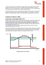
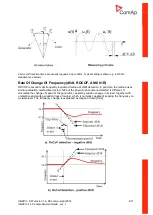
In order to prevent from unwanted voltage oscillation around the overvoltage, respective undervoltage
limits, there is a possibility to set up voltage hysteresis. The principle is shown in the pictures below.
After overvoltage situation, voltage must decrease under the hysteresis limit to clear the fault. After
undervoltage situation, voltage must exceed the hysteresis limit to clear the fault.
Time (s)
Pick up value
Measured value
H
ys
te
re
si
s
Pick up
Hysteresis limit
Drop off
Voltage (V)
Voltage hysteresis for overvoltage


