InteliLite Global Guide
123
Working with the editor
If the currently opened archive does not contain any PLC program, then an empty drawing is created
automatically when you select the PLC Editor. The procedure of creation of a PLC drawing (program) contains
following essential steps:
Adjust the sheet to your needs. See
Working with sheets (page 123)
for more information.
Add PLC blocks into the sheets. See
for more information.
Define inputs and outputs of the PLC program. See
Define inputs and outputs (page 124)
for more
information.
Create connections between inputs, blocks and outputs. See
for more
information.
Adjust properties of the blocks. See
for more information about blocks.
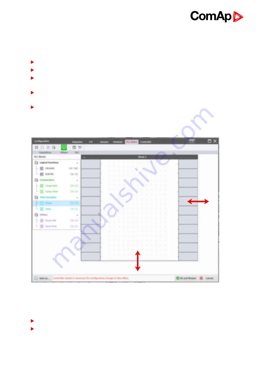
Working with sheets
Drag the sheet edges to re-size the sheet according to your needs.
Image 5.33 Adjusting PLC sheet
Adding PLC blocks
Adding PLC block is simple and intuitive. Follow the procedure below to add PLC block.
Select required block from the list of available PLC blocks at the left and drag it into the sheet.
Double-click on the block and adjust properties of the block. See
for more
information about blocks.
Summary of Contents for InteliLite AMF25
Page 34: ...InteliLite Global Guide 34 ConnectionType SplPhL1L2 Image 4 11 Split phase L1L2 application ...
Page 36: ...InteliLite Global Guide 36 Image 4 14 Typical Split Phase generator wiring ...
Page 91: ...InteliLite Global Guide 91 Image 5 13 Flowchart of start of diesel engine ...
Page 93: ...InteliLite Global Guide 93 Image 5 14 Flowchart of start of gas engine ...
Page 721: ...InteliLite Global Guide 721 Image 9 34 IGS PTM Image 9 35 IGS PTM dimensions ...
Page 727: ...InteliLite Global Guide 727 Image 9 36 Inteli AIN8TC Image 9 37 Inteli AIN8TC dimensions ...
Page 731: ...InteliLite Global Guide 731 Image 9 38 Inteli AIO9 1 Image 9 39 Inteli AIO9 1 dimensions ...


