37
MACHINE
PREP
ARA
TION
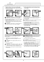
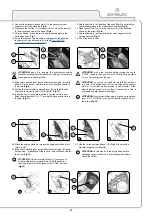
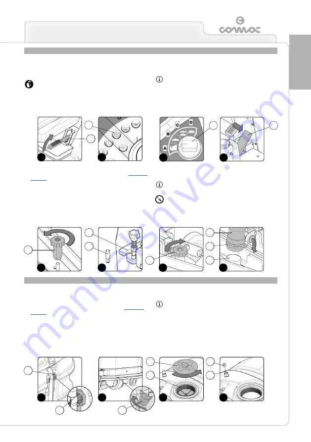
ASSEMBLING THE SQUEEGEE
For reasons of packaging, the squeegee is supplied dismantled
from the machine. To fit it on the side bars, proceed as follows:
1. Bring the machine to the maintenance area.
ATTENTION:
these operations must be carried out using
protective gloves to avoid any possible contact with the edges
or tips of metal objects.
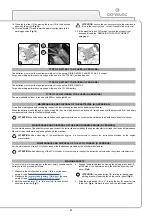
2. Engage the parking brake by moving the parking brake lever (1)
(at the side of the operator seat) in the direction shown by the
arrow (
Fig.1
).
ATTENTION:
the indicator light (2) relating to the engaged
parking brake will be activated on the control panel (
Fig.2
).
3. Use the i-drive adjustment switch (3) to select the “transfer”
program (A) (
Fig.3
).
4. Press the drive pedal (4) to bring the brush heads to their idle
position (
Fig.4
).
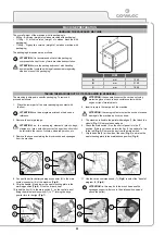
FILLING THE SOLUTION TANK
Before filling the solution tank, carry out the following steps:
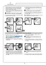
1.
Bring the machine to the area designated for refilling the solution
tank.
2. Make sure the machine is in a safe condition (read “
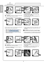
3. Make sure the cap (1) of the solution tank drainage tube (2) is
properly tightened (
Fig.1
).
4.
Make sure the cap of the water system filter (3) is properly
tightened (
Fig.2
).
5. Remove the solution tank cap (4) (
Fig.3
). Make sure the filter (5)
is correctly positioned (
Fig.3
).
6. Fill with clean water, at a temperature no higher than 50°C and
no lower than 10°C.
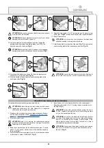
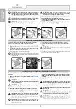
ATTENTION:
the tank can be refilled using the optional quick
refilling system which includes a float to avoid any risk of
overflow. This avoids the need to continuously check the
water level. To enable this system, just remove the solution
tank cap (6) (
Fig.4
) and insert the modified water tube in the
quick connection (7). Remember to loosen the cap (4) to
ensure good air venting.
5. As soon as the brush head is in the idle position, switch off the
machine and make sure it is in a safe condition (read “
MACHINE
SAFETY
”).
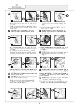
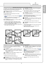
6. Remove the knobs (5) from the squeegee unit (
Fig.5
).
7. Insert the squeegee unit in the squeegee support, making sure
the pins (6) on the unit enter the slots (7) on the support (
Fig.6
).
8. Fix the unit to the support by replacing and then tightening the
knobs (5) (
Fig.7
).
9. Insert the squeegee vacuum tube (8) in the nozzle (9) on the
squeegee unit (
Fig.8
).
ATTENTION:
remember to loosen the screw clamp (10) on
the vacuum tube before inserting it in the nozzle (
Fig.8
).
ATTENTION:
the equipment to be used for this operation is
not supplied with the machine.
7
8
5
6
3
4
1
2
1
1
1
1
1
1
1
1
1
1
1
1
1
1
2
1
5
2
4
6
5
7
5
6
10
9
7
8
2
3
4
3
4
1
1
1
3
Summary of Contents for ULTRA 120 B-G
Page 2: ......
Page 7: ...7 36 72 102 6 9 10 110 107 106 75 5 76 74 58 7 59 7...
Page 9: ...9 103 4 56 31 43 109 15 3 98 22 65 24 108 19 34 35 23 68 44 63 64 99...
Page 10: ...10 2 94 17 101 96 105 69 12 11 18 73 40 97 95 104 42...
Page 68: ...68 NOTES...
Page 69: ...69 NOTES...
Page 70: ...70 NOTES...
Page 71: ......

