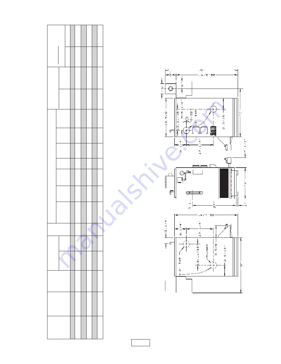
Columbia CEG-C Installation Manual And Operating Instructions Download Page 28

FRONT VIEW

LEFT SIDE VIEW

RIGHT SIDE VIEW

37411601

PAGE 26

REV: 8, December 2001

RARARARARA

TINGSTINGSTINGSTINGSTINGS

,,,,, D D D D D

AAAAA

TTTTTA,A,A,A,A,


AND DIMENSIONSAND DIMENSIONSAND DIMENSIONSAND DIMENSIONSAND DIMENSIONS

NATURAL GAS STEAM BOILERSNATURAL GAS STEAM BOILERSNATURAL GAS STEAM BOILERSNATURAL GAS STEAM BOILERSNATURAL GAS STEAM BOILERS

*A.G.A

Heating

Net I=B=R**

G

a

s

Dimensions

WATER CONTENT

Annual Fuel

Boiler

Input

Capacity

Steam Rating

Inlet

(GALLON CAPACITY)

Utilization

 Efficiency

Number

Btu/Hr.

Btu/Hr.

Btu/Hr.

Sq. 

Ft.

Size

A

B

C

D

E

F

G

To 

Water

 To LWCO

(AFUE)

& Damper

& Damper

Line

Line

Elect Ign

Std. 

Pilot

CEG112C

112,500

90,000

67,500

28

1

1/

2

14.1/4

27.5/8

24.1/8

5

3.1/2

6

44.3/4

4.

8

3.

0

81

.0

78

CEG150C

150,000

120,000

90,000

37

5

1/

2

17.1/8

28.5/8

24.5/8

6

4

6.1/2

45.1/4

6.

0

3.

7

81

.0

78

CEG187C

187,000

151,000

113,300

47

2

1/

2

20

29.5/8

25.1/8

7

4.1/2

7

45.3/4

7.

0

4.

4

81

.0

78

CEG225C

225,000

181,000

135,800

55

6

3/

4

22.13/16

30.5/8

25.5/8

8

5

8

46.3/4

8.

4

5.

0

81

.0

78

CEG262C

262,500

212,000

159,000

66

3

3/

4

25.5/8

30.5/8

25.5/8

8

5

8

46.3/4

9.

5

5.

8

81

.0

78

CEG300C

299,999

243,000

182,300

76

0

3/

4

28.1/8

31.5/8

26.1/8

9

5.1/2

10

48.3/4

10.7

6.4

81.0

78

NOTE:

For altitudes above 2,000 ft. ratings should be reduced at the rate of 4% for each 1,000 ft. above sea level, The MEA number for the CEG series is 17-79. Electrical service to be 120 Volts, 15 Amps, 60 Hz. **For equivalent square feet of radiation, divide I=B=R output by 240.

STANDARD EQUIPMENT:

 Crafted Boiler, Drafthood, Low Water Cut-off (Probe Type), Deluxe Jacket, Wiring, Automatic Vent Damper, Ported Stainless Stee

l Burners,

Blocked Vent and Roll-Out Safety Switches, Gas Valve, Pilot, Pressure High Limit Control, 2-2" Supply Tapping-L.H. Plugged, 2-2

" Return Tappings-L.H. Plugged.

Packed in Separate Carton:Pop Safety Valve and Boiler Drain.

OPTIONAL EQUIPMENT:

 Electronic water feeder

The Ratings marked “Net I=B=R” indicate the amount of equivalent direct cast iron radiation each boiler will take care of under

 normal conditions and thermostatic control. The

Net I=B=R Steam Ratings shown are based on a piping and pickup allowance of 1.333. Proper allowance has been made for piping an

d pickup in accordance with the

factors shown in the I=B=R Standard as published by The Hydronics Institute.

Selection of boiler size should be based upon Net BTU per Hour of the connected radiation and piping. The manufacturer should be consulted before selecting a boiler for installations having unusual piping and pickup requirements. In line with it's policy of product improvement, Columbia Boilers reserves the right to make changes without notice.

Summary of Contents for CEG-C

Page 1: ...ON MANUAL AL AL AL AL AND OPERA AND OPERA AND OPERA AND OPERA AND OPERATING INSTR TING INSTR TING INSTR TING INSTR TING INSTRUCTIONS UCTIONS UCTIONS UCTIONS UCTIONS CEG C CEG C CEG C CEG C CEG C GAS FIRED BOILERS FOR STEAM HEATING Columbia Boiler Company Main Offices and Factory Pottstown PA ...

Page 2: ...0 Electrical Wiring Page 10 Thermostat Installation Page 11 Lighting Instructions Pages 11 13 Normal Sequence of Operation Page 14 Connecting Supply And Return Piping Water Chilled Medium Page 15 General Instructions Pages 16 20 Replacement Parts Lists Pages 20 25 Ratings Data and Dimensions Page 26 KEEP THIS MANUAL NEAR BOILER RETAIN FOR FUTURE REFERENCE SERIES CEG C CAST IRON GAS FIRED BOILERS I...

Page 3: ...E ONLY BY A QUALIFIED EXPERT AND IN SHOULD BE DONE ONLY BY A QUALIFIED EXPERT AND IN ACCORDANCE WITH THE APPROPRIATE COLUMBIA BOILERS ACCORDANCE WITH THE APPROPRIATE COLUMBIA BOILERS ACCORDANCE WITH THE APPROPRIATE COLUMBIA BOILERS ACCORDANCE WITH THE APPROPRIATE COLUMBIA BOILERS ACCORDANCE WITH THE APPROPRIATE COLUMBIA BOILERS MANUAL INSTALLING OR VENTING A BOILER OR ANY OTHER GAS MANUAL INSTALLI...

Page 4: ... National Fuel Gas Code noted above or applicable provisions of the local building codes See Vent Installation on page 7 4 This boiler meets safe lighting and other preference criteria with the gas manifold and control assembly provided on the boiler per the latest revision of ANSI Z21 13b 5 This boiler shall be installed such that the gas ignition system components are protected from water drippi...

Page 5: ...on 1 7 the boiler area shouldbeconsideredasaconfinedspace Inthiscaseairforcombustionandventilationshall be provided according to part 5 below If there is any doubt install air supply provisions in accordance with the latest revision of the National Fuel Gas Code 3 Whenaboilerisinstalledinanunconfined space in a building of unusually tight construction airforcombustionandventilation must be obtaine...

Page 6: ...ing shall have a minimumfreeareaof1squareinchper4 000 BTU per hour of total input rating of all equipment in the enclosure See figure 2 below 2 When communicating with the outdoors by means of vertical ducts each opening shall have a minimum free area 1 square inch per 4 000 BTU per hour of total input rating of all appliances in the enclosed space See figure 3 above 3 If horizontal ducts are used...

Page 7: ...ese Tees arenecessaryforproper cleaning and servicing of the boiler 5 For further piping information refer to the I B R installation piping guide PAGE 5 FIGURE 5 SUGGESTED PIPING FOR A SINGLE STEAM BOILER HEATING SYSTEM input rating of all equipment located in the enclosure The free area must be no less than the sum of the areas of all vent connectors in the confined space 6 In calculating free ar...

Page 8: ...PAGE 6 FIGURE 6b SUGGESTED PIPING FOR A MODULAR STEAM BOILERS PUMPED RETURNS GRAVITY RETURNS FIGURE 6a ...

Page 9: ...G WARNING ALL ALL ALL ALL ALL INSTALLATIONS OF BOILERS INSTALLATIONS OF BOILERS INSTALLATIONS OF BOILERS INSTALLATIONS OF BOILERS INSTALLATIONS OF BOILERS AND VENTING SHOULD BE AND VENTING SHOULD BE AND VENTING SHOULD BE AND VENTING SHOULD BE AND VENTING SHOULD BE DONE ONLY BY A QUALIFIED DONE ONLY BY A QUALIFIED DONE ONLY BY A QUALIFIED DONE ONLY BY A QUALIFIED DONE ONLY BY A QUALIFIED EXPERT AND...

Page 10: ...ated and other spaces in the building Turn on clothes dryers and any appliance not connected to the common venting system Turn on any exhaust fans such as range hoods and bathroom exhausts so they will operate at maximum speed Do not operate a summer exhaust fan Close fireplace damper D Place in operation the appliance being inspected Follow the lighting instructions Adjust thermostat so appliance...

Page 11: ...TRUCTIONS INSTRUCTIONS INSTRUCTIONS INSTRUCTIONS 1 Ensure that only the boiler is serviced by the Vent Damper See figure 9 above 2 Clearance of not less than 6 inches between Vent Damper and combustible construction must be maintained Additional clearance should be allowed for service of the Vent Damper 3 Vent Damper must be in open position when appliance main burners are operating 4 The Vent Dam...

Page 12: ...ion To check for leaks in gas piping use a soap and water solution or other approved method W W W W WARNING ARNING ARNING ARNING ARNING DO NOT USE AN OPEN FLAME 3 The boiler and its individual shutoff valve must be disconnected from the gas supply piping system during any pressure testing of that system at test pressures in excess of 1 2 psi 3 5 kPa The boiler must beisolatedfromthegassupplypiping...

Page 13: ...wall at least two feet from an uninsulated or outside wall approximately four feet above the floor 2 NEVER install a thermostat on an outside wall 3 Do not install a thermostat where it will be affected by A Drafts B Hot or cold pipes C Sun light D Lighting fixtures E Television F Fireplace or chimneys 4 Check thermostat operation by raising and lowering thermostat as required to start and stop th...

Page 14: ...trol knob counterclockwise to ON 9 Replace control access panel IF PRESENT 10 Turn on all electric power to the appliance 11 Set thermostat to desired setting 12 If the appliance will not operate follow the instructions To Turn Off Gas To Appliance and call a qualified service technician or your gas supplier LIGHTING PROCEDURE FOR BOILER WITH LIGHTING PROCEDURE FOR BOILER WITH LIGHTING PROCEDURE F...

Page 15: ... on the base or on one of the burner tubes 8 Turn gas control knob counterclockwise to pilot 9 Push in gas control knob or reset button if so equipped all the way in and hold ImmediatelyLightthepilotwithamatch Continuetoholdthegascontrolknoborresetbutton for about one 1 minute after the pilot is lit Release knob or button and it will pop back up Pilot should remain lit If it goes out repeat steps ...

Page 16: ...ntil the steam pressure drops below the pressure control setting 4 In the event a low water condition occurs an automatic low water cut off device will interrupt the circuit to the ignition system until the low water condition is satisfied i e manually restore the water or utilize an electric water feeding device which will automatically restore boiler water to its normal operating level 5 In the ...

Page 17: ...lves C and D Close valves A and B C Maintain a minimum clearance of one inch between combustible materials and hot water pipes Reduced pressure backflow preventer must be present under provisions required by the Environmental Protection Agency EPA 2 When the boiler is connected to heating coils located in air handling units where they may be exposed to refrigerated air circulation the boiler pipin...

Page 18: ...oes not open it must be replaced If the safety valve leaks steam when the boiler is operating at normal pressures it should be immediately replaced Corrosion can build up rapidly at the valve seat and prevent its functioning as a safety device Duringtheheatingseasonthedraincock on the bottom rear of the boiler should be opened once a month to flush out the boiler so the device will be free to func...

Page 19: ...position UseboilerputtyorGEIS 808siliconetosealaroundthefluecollectorandcastings Makecertaintheburnerendsareinsertedintheslotsatthebackofthecombustionchamber and well down in position over the burner orifices Follow the lighting instructions on the boiler to put the burners back in operation CHECK SAFETY CONTROL CIRCUIT CHECK SAFETY CONTROL CIRCUIT CHECK SAFETY CONTROL CIRCUIT CHECK SAFETY CONTROL...

Page 20: ...ke sure it is free from oil by drawing off a sample at the skimming tee If the sample is reasonably free from oil it will not froth when boiled on stove This test does not indicate the amount of sediment which may lay in the bottom of the boiler It is therefore necessary that the boiler be further cleaned by blowing down BLOWING DOWN BOILER BLOWING DOWN BOILER BLOWING DOWN BOILER BLOWING DOWN BOIL...

Page 21: ...ll other gas appliances off determine the flow of gas through the meter for two minutes and multiply by 30 to get the hourly rate Make minor adjustments to the gas input as described above Primary air adjustment is not necessary therefore air shutters are not furnished as standard equipment Air shutters can be furnished on request when required by local codes or conditions A visual check of the ma...

Page 22: ...d boiler room should not be restricted or blocked It is suggested that a qualified service agency be employed to make an annual inspection of the boiler and heating system They are experienced in making the inspections outlined above and in the event repairs or corrections are necessary can make the proper changes for safe operation of the boiler Optional parts WC 001 00 67 U LWCO WC 004 01 101 Wa...

Page 23: ...10 CEG 225 12 CEG262 14 CEG300 16 4 32425301 BASEPLATECEG112C 32425302 BASEPLATECEG150C 32425304 BASEPLATECEG225C 32425305 BASEPLATECEG262C 32425306 BASEPLATECEG300C 5 5612501 BASEWITHINSULCEG112C 1 5612502 BASEWITHINSULCEG150C 5612503 BASEWITHINSULCEG187C 5612504 BASEWITHINSULCEG225C 5612505 BASEWITHINSULCEG262C 5612506 BASEWITHINSULCEG300C 6 3342701 BURNER ASSY W PILOT 1 BRACKETANDSHUTTER 7 3342...

Page 24: ...2703 FLUE COLLECTOR CEG150C 3442704 FLUE COLLECTOR CEG187C 3442705 FLUE COLLECTOR CEG225C 3442706 FLUE COLLECTOR CEG262C 3442707 FLUE COLLECTOR CEG300C 6 344 2 1 02 DRAFT HOOD CEG112C 1 344 2 1 03 DRAFT HOOD CEG150C 344 2 1 04 DRAFT HOOD CEG187C 344 2 1 05 DRAFT HOOD CEG225C 344 2 1 06 DRAFT HOOD CEG262C 344 2 1 07 DRAFT HOOD CEG300C 7 31423302 REARPANELCEG112C 1 31423303 REARPANELCEG150C 31423304...

Page 25: ...1 4X13 CEG150 HW 011 04 TIE ROD 1 4X17 CEG187 HW 011 05 TIE ROD 1 4X19 CEG225 HW 011 07 TIE ROD 1 4X23 CEG262 HW 011 08 TIE ROD 1 4X25 CEG300 6 PF 007 02 PIPE FIT PLG 2 1 7 251 1 2 00 J BOLT 1 4 20X3 5 16 2 8 100 1 1 01 PUSH NIPPLE 3 MACH CEG112C 4 CEG150 6 CEG187 8 CEG 225 10 CEG262 12 CEG300 14 9 HW 016 02 DRAIN LONG 1 10 1570001 VALVE POP SAFETY 3 4 1 11 1150001 COUPLING3 4 1 12 PF 005 10 PIPE ...

Page 26: ... 3 WCO1901 ELWCOPS 802U 24 1 WITH PROBE 4 HW 006 02 POP RIVIT FLUE 3 16 2 5 32421901 SENSORBRACKET 1 6 AQ02101 CONTROLFIXEDTEMP 2 ONEONDRAFTHOOD 7 37513301 WIRE ROLL OUT 1 8 HW06501 SCR 6X1 4 SLOT 2 ITEM PART NUMBER DESCRIPTION OTY 9 753 1 3 00 90 SYPHON 1 10 PF 025 01 1 4 TEE 1 11 PF 026 05 1 4 X 3 NIPPLE 1 12 GA 003 00 PRESSUREGAUGE 1 13 PF 027 01 1 4 ELBOW 90 1 14 SS 001 01 PRESSURESWITCH 1 15 ...

Page 27: ...414401 WIRE PRES SWITCH TO J BOX 34 1 3 37424501 HARNESS ELWCO TO J BOX 18 1 4 PB00702 IGN WIRE 30 CIDE MODELS ONLY 1 5 37413602 HARNESS IGN MOD TO GAS VALVE 12 1 6 PB00604 SPKCTLS8600M1013 1 7 37413201 WIRE SPILL SWITCH 47 1 8 37413801 WIRE J BOX TO CONTROLS 27 1 9 EF03601 WIRE CLAMP 3600 WHITE 1 10 37413002 WIRETRANSFORMER WHITE 15 1 11 37413001 WIRETRANSFORMER BROWN 15 1 12 3641601 TRANSFORMER ...

Page 28: ...s above 2 000 ft ratings should be reduced at the rate of 4 for each 1 000 ft above sea level The MEA number for the CEG series is 17 79 Electrical service to be 120 Volts 15 Amps 60 Hz For equivalent square feet of radiation divide I B R output by 240 STANDARD EQUIPMENT Crafted Boiler Drafthood Low Water Cut off Probe Type Deluxe Jacket Wiring Automatic Vent Damper Ported Stainless Steel Burners ...

Reviews: