Page 93
Ci Scanner Service Manual
16.
NETWORK CONFIGURATION
16.1.
NETWORK COMPONENTS
DHCP Server
The DHCP Server manages the IP addresses of LAN components.
Normally the DHCP Server is the LAN boundary router but can be a
dedicated server. The Ci scanner does not support plug and play. For
error free operation, to avoid IP conflicts, configure the DHCP Server to
associate the Ci scanner's allocated IP with its MAC address.
IP Filters/Firewalls
Some firewalls and IP filters can restrict connectivity between the PC and
the Ci scanner. Firewalls, whether client of network based, and IP filters,
must be configured to permit a TCP protocol connection between the PC
and ports 17236 (command) and 17237 (data) on the scanner. If different
port numbers are used, firewalls should be programmed to accommodate
these.
Network devices
Routers are network boundary devices. It should not be necessary to
connect a PC to a Ci scanner through a router. It will be necessary to
connect these through network hubs and switches. Either a hub, or the
switch, connected to the scanner must be capable of Gbit. Connectivity
cannot be established using 100Mbit, Fast Ethernet devices. For the best
results, the connectivity between the PC and the Ci scanner should be
over Gbit throughout.
Connecting cables
Cables connecting the Ci scanner to network devices must be to the
standard Cat5e and Cat6.
16.2.
NETWORK CONFIGURATION
Best practice
When the Ci scanner downloads a scan to a PC, it transfers a significant
amount of data. This activity can significantly increase the network load.
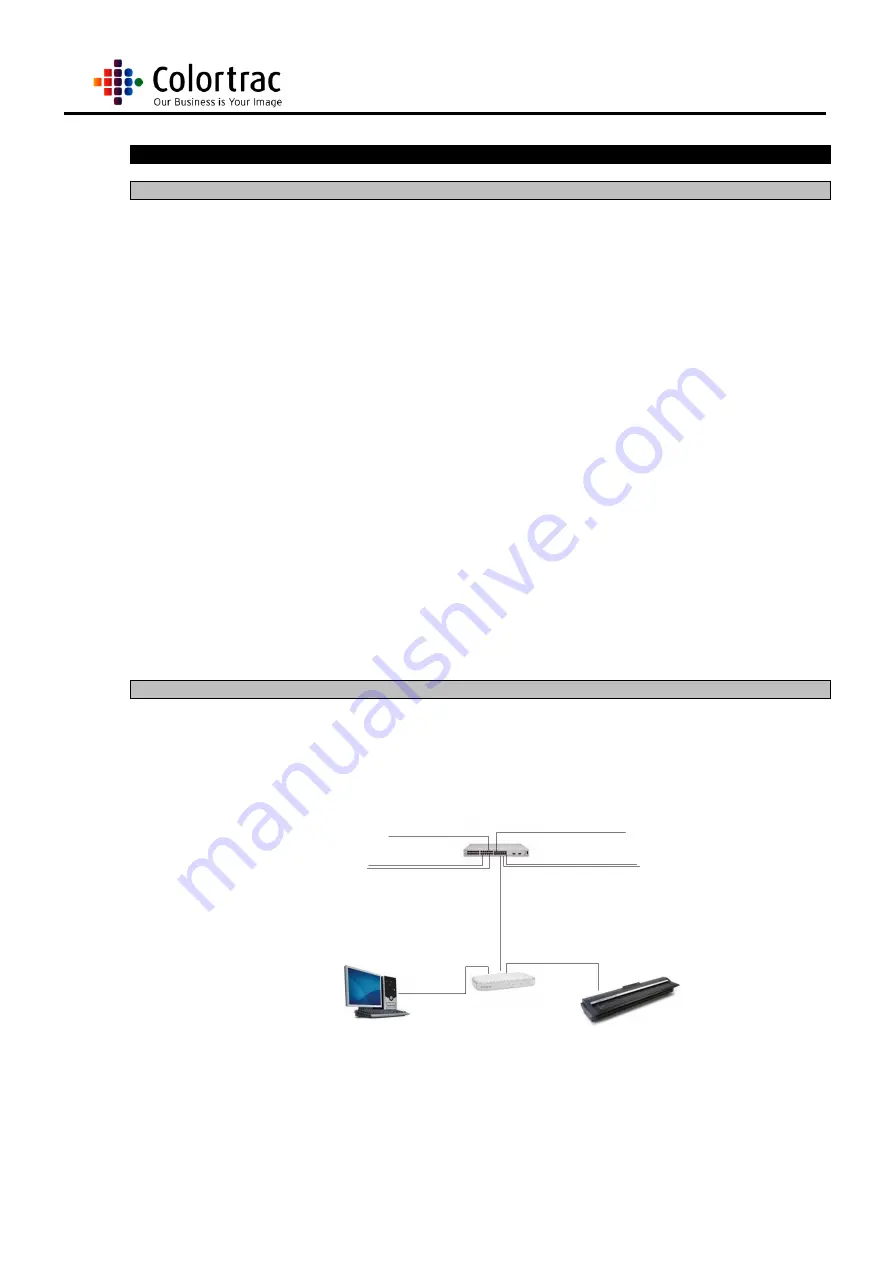
Best practice is to connect the Ci scanner to a PC through a switch spur.
Should a hub be used, the main network would still be loaded
unnecessarily.
The effects of network
loading
It can take several minutes to download data from a scan to a PC via the
LAN. This time can increase significantly if the network load is already
high, particularly during network antivirus operations or at the beginning
and end of the working day. Be connecting the Scanner to the PC using a
switch spur these effects can be minimised.
Summary of Contents for SmartLF Ci 40
Page 12: ...Page 12 Ci Scanner Service Manual...
Page 40: ...Page 40 Ci Scanner Service Manual 13 Close the Lid Unit...
Page 45: ...Page 45 Ci Scanner Service Manual 7 Close the Lid Unit...
Page 96: ...Page 96 Ci Scanner Service Manual...
Page 97: ...Page 97 Ci Scanner Service Manual...
Page 98: ...Page 98 Ci Scanner Service Manual 17 4 MAIN BOARD...
Page 99: ...Page 99 Ci Scanner Service Manual...
Page 100: ...Page 100 Ci Scanner Service Manual...


