background image


Page 88 


Ci Scanner Service Manual


14. 

UPGRADING 


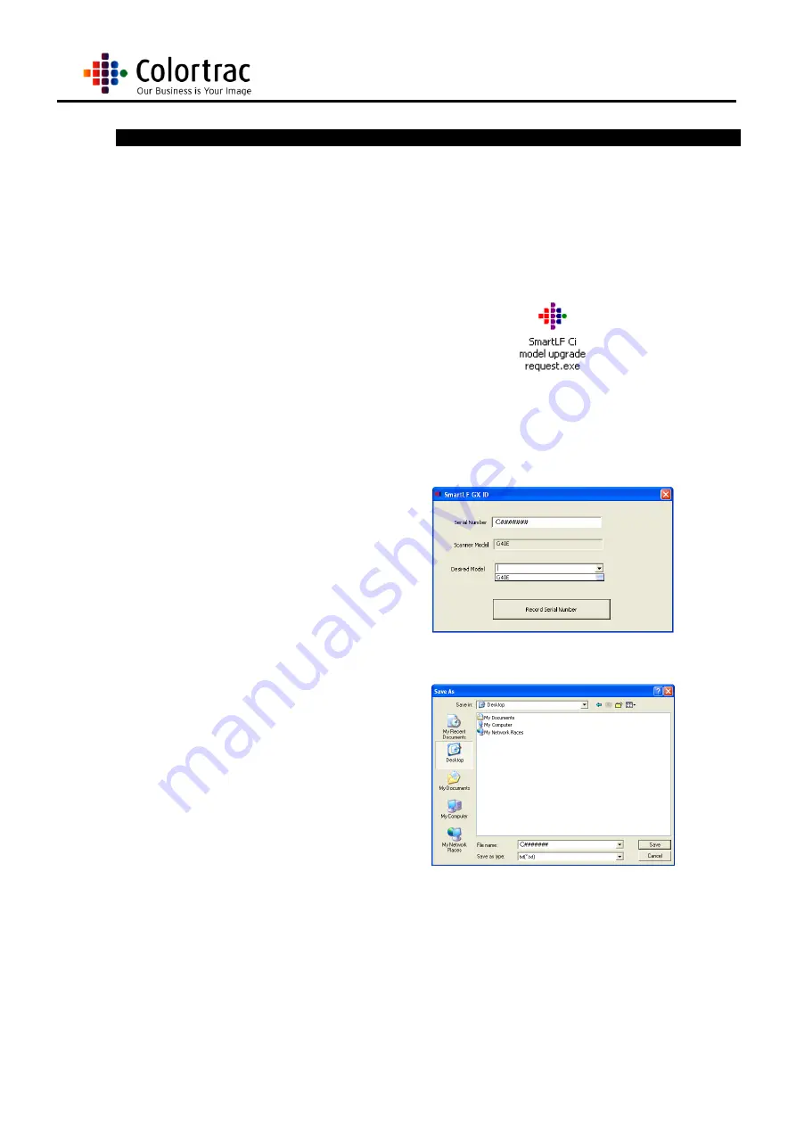
1.  Ensure your Ci scanner is 

connected to your PC and 
the scanner driver and 
utilities are installed. 


2.  Insert the Installation CD 

provided with the scanner 
and select the upgrade 
utility  


3.  Enter your scanners serial 

number into the 
appropriate field and select 
the model you require 
using the drop down and 
scroll buttons.  Then select 
'Record Serial Number' 


4.  The utility creates a coded 

text file that contains 
details of the upgrade you 
require.  Enter a name for 
the file and select a 
location for it.  We 
recommend you select a 
file name that contains the 
scanner serial number and, 
for ease of use, you save 
the file to your Desktop. 


5.  Email the saved txt file to 

[email protected]

 along with a purchase order for 

the upgrade. 

6.  You will then receive an email containing a zipped file, which when unzipped provides an 

executable file. 

7.  Ensuring the right scanner is connected initiate the executable file. 

8.  The scanner is now upgraded to the selected standard. 

Summary of Contents for SmartLF Ci 40

Page 1: ...04 15 This is a confidential controlled document and is the property of Colortrac Ltd It is not to be copied or reproduced in part or whole It is intended for staff to read S Sm ma ar rt tL LF F C Ci...

Page 2: ...tions should be reported to Technical Support Colortrac Ltd Colortrac Ltd shall not be liable for any damages errors issues or events that result from the use of the equipment or this manual No part o...

Page 3: ...ht 8 5 1 4 Rotating Rollers 8 5 2 EMC TESTING 8 6 SCANNER CAUTIONS 9 7 WARRANTY 10 7 1 WARRANTY PERIOD 10 7 2 CONSUMABLES 10 7 3 CIS REPLACEMENT UNDER WARRANTY 10 7 4 PURCHASE OF CIS 10 8 CIS TECHNOLO...

Page 4: ...WITCH 74 13 UTILITIES PROGRAMS 81 13 1 INSTALLATION 81 13 2 CONFIGURING THE MAIN BOARD 82 13 3 RUNNING UTILITIES 83 13 4 NORMALISATION 86 13 5 AUTO STITCH 87 14 UPGRADING 88 15 HELP DESK 89 15 1 EXTEN...

Page 5: ...x CIS Arrays SmartLF Ci24e Enhanced Scan width of 24 inches Handles 25 67 inch media Optical resolution of 600 dpi RGB 24 bit and 48 bit captured at enhanced speed Mono and greyscale scanning Contain...

Page 6: ...Key 3 3mm Allen Key or 3mm Hex Key 4 Pliers Flat nosed pliers short serrated 5 7mm Nutdriver To remove and fit M5 nuts 6 Medium Pozi drive screwdriver PZ1 x 80mm length 7 Small Pozi drive screwdriver...

Page 7: ...ask Users who log in for the first time to update their profile Some information we require and some we leave to the Users discretion to provide But the more complete the information provided the bett...

Page 8: ...5 minutes to discharge before removing covers and any of the boards The boards may hold a charge and may give a shock if touched Please observe anti static precaution when handling any electrical boa...

Page 9: ...surface Do not scan thick or rigid media Do not unplug the scanner during a scan sequence Do not let an end user remove any panels from the scanner Do not use any other power supply other than the app...

Page 10: ...ac Help Desk and selecting Notification of Installation Date see Chapter 15 1 On how to extend warranty 7 2 CONSUMABLES Parts that wear according to operator usage are deemed consumables and not repla...

Page 11: ...best performance in terms of resolving power and geometric accuracy The illumination is provided by Light Emitting Diodes LED s shining down a light guide which in turn directs the light onto the doc...

Page 12: ...Page 12 Ci Scanner Service Manual...

Page 13: ...C field precedes each packet to allow the receiver s to synchronise their bit recovery clocks The cable also carries VBUS and GND wires on each segment to deliver power to devices VBUS is nominally 5...

Page 14: ...SUPPLY AC I P 100 240V 1 5A 50 60 Hz DC O P 19V 3 42A NOTE Only use the Ci scanner Power Supply Unit provided by Colortrac Ltd for operating the Ci scanner The use of alternative power sources may be...

Page 15: ...ORMATION 10 1 BLOCK DIAGRAM Consists of 3 or 5 x CIS Arrays 4 x Paper Sensors 1 x USB Connector 1 x Stepper Motor 1 x Power I P Connector 1 x Mains Switch 1 x Main Board 1 x Lid Cut Off Micro Switch 1...

Page 16: ...media side justified and centre justified Before scanning ensure the software is set to the correct preference and the media is inserted at the correct position as indicated on the Paper Tray Sub A In...

Page 17: ...he stand if used NOTE Images in this chapter show the Ci24 scanner Carry out the same procedure for the Ci40 2 Lift the scanner from the stand and rotate onto its back 2 people are required to lift th...

Page 18: ...he stand while in the maintainence poistion 6 To return the scanner back to its operating position first remove the 2 x M5 bolts securing it to the stand 7 Lift and rotate the scanner back to it s nor...

Page 19: ...disconnected from the scanner unit Ensure the scanner is positioned on its Colortrac stand or a stable maintenance platform 11 1 2 Tools Medium pozi drive screwdriver 11 1 3 Associated Part Numbers P...

Page 20: ...Page 20 Ci Scanner Service Manual 3 Before refitting the side panel make sure the wires and cables are not damaged or trapped 4 Replace the 5 x M5 Pan Head screws and tighten...

Page 21: ...re the scanner is positioned on its Colortrac stand or a stable maintenance platform 11 2 2 Tools Small pozi drive screwdriver Medium pozi drive screwdriver 11 2 3 Associated Part Numbers P003128 Righ...

Page 22: ...ables 3 Slowly pull the end cover away from the chassis Ensure that the Right end cover remains supported and is not allowed to hang suspended by the connected wires 4 Remove the connector panel from...

Page 23: ...age 23 Ci Scanner Service Manual 6 Replace the 4 x M3 CSK screws to hold the connector panel in the end cover 7 Replace the end cover on to the chassis 8 Replace the 5 x M5 Pan Head Screws and tighten...

Page 24: ...is positioned on its Colortrac stand or a stable maintenance platform 11 3 2 Tools Medium Pozi drive screwdriver Medium Stubby Pozi drive screwdriver 11 3 3 Associated Part Numbers P003273 Ci40 Lid C...

Page 25: ...the screws While bending the Mylar back to remove the screw care is to be taken not to crease or damage the Mylar Should it be creased or damaged the Mylar strip should be replaced 4 Close the lid uni...

Page 26: ...n Sub A on top of the lid unit and replace the 5 x M4 Pan Head screws 7 Press the locking buttons and open the lid unit 8 Replace the 4 x M4 Pan Head screws under the Mylar strip Being careful not to...

Page 27: ...set of screws to raise the lid cover 10 To raise the Lid Cover Extrusion Sub A loosen the 4 x holding screws in the elongated holes Then tighten the adjust screw next to it to push the lid further awa...

Page 28: ...2 Tools Medium Pozi drive screwdriver 11 4 3 Associated Part Numbers P003322 Ci40 PCB Tray Sub A P003329 Ci40 Cable Tray Right Sub A P003505 Ci24 PCB Tray Sub A 11 4 4 Procedure 1 Ensure the scanner...

Page 29: ...ight Sub A away from the chassis 4 Remove the 4 x M3 pan head screws from the PCB Tray covering the Main Board NOTE The bottom right hand corner screw acts as an earth point 5 Disconnect the Ethernet...

Page 30: ...cover with suppressors the wires are hard soldered on and can be easily broken off and so great care is needed when handling this cable A soldering iron is required to change the suppressors so it is...

Page 31: ...t the main connector onto the main board making sure it latches in place 11 Refit the PCB Tray by making sure that all the fitted cables are out of the way of any edges of the cover Feed the large rib...

Page 32: ...x M3 pan head screw to hold the cover on remembering to fit the earth lead to the bottom right hand screw 13 Reconnect the mains cable together making sure the latch locks in place 14 Reconnect the E...

Page 33: ...able Tray Right Sub A making sure the left hand end is fed on first Make sure the ribbon cable is not caught on the metal tray when fitting 17 Refit the 6 x M3 pan head screw to hold the Cable Tray Ri...

Page 34: ...vice Manual Ci24 18 For the Ci24 PCB Tray remove the 4 x M3 screws in each corner 19 Pull the PCB tray out gently remembering the power cable is connected to the tray 20 Disconnect the inline connecto...

Page 35: ...ct the Power cable from the main board 22 To refit the PCB Tray reconnect the power cable into the main board 23 Reconnect the inline power cable connector 24 Reposition the PCB Tray making sure that...

Page 36: ...e 36 Ci Scanner Service Manual 25 Replace the 4 x M3 screws in each corner of the PCB Tray 26 Rotate the scanner back into position on the stand as described in chapter 10 3 Scanner Maintenance Positi...

Page 37: ...nce platform 11 5 2 Tools Small pozi drive screwdriver 11 5 3 Associated Part Numbers P003355 Ci40 Paper Tray Sub A non magnetic P003506 Ci24 Paper Tray Sub A non magnetic P003812 Ci24 Paper Tray Sub...

Page 38: ...It may be necessary to loosen the belt tension bar to remove the Pan head screw nearest it To do this follow the instructions at Chapter 12 1 Main Timing Belt 7 Pull the Paper Tray Sub A towards the...

Page 39: ...er hanging the scanner by 1 Then slide the Paper Tray Sub A back into position 10 Replace the 4 x M4 Pan Head screws on either end of the scanner It may be necessary to re tension the belt if it has b...

Page 40: ...Page 40 Ci Scanner Service Manual 13 Close the Lid Unit...

Page 41: ...orm 12 1 2 Tools 7mm Nutdriver 12 1 3 Associated Part Numbers P003151 Main Timing Belt 12 1 4 Procedures 1 Remove left end cover as in Chapter 11 1 2 Loosen the locking nut on the tension bar Do not a...

Page 42: ...il the belt is fully on 5 Using one finger apply pressure on the tension bar to remove any slack in the belt Tighten the nut on the end of the tension bar to lock it to position Do not over tighten th...

Page 43: ...positioned on a stable maintenance platform 12 2 2 Tools None 12 2 3 Associated Part Numbers P003365 Ci40 Mylar Paper Guide Sub A P003510 Ci24 Mylar Paper Guide Sub A 12 2 4 Procedures 1 Press down o...

Page 44: ...pletely 5 Position the Mylar strip to the lid assembly so the edge of the Mylar is against the ridge of the lid assembly and the end of the Mylar is level with the end of the lid assembly 6 Peal all t...

Page 45: ...Page 45 Ci Scanner Service Manual 7 Close the Lid Unit...

Page 46: ...um pozi drive screwdriver 12 3 3 Associated Part Numbers P003319 Roller Shaft Pulley Sub A P003151 Main Timing Belt 12 2 4 Procedures 1 Remove left end cover as in Chapter 11 1 2 Remove Main Timing Be...

Page 47: ...ut for the shaft key NOTE The M4 x 8 screw goes into the hole at the shaft key cut out and the M4 x 10 in the hole opposite the cut out When the shaft key is fitted insert it so the flat side is face...

Page 48: ...he spring for the lid unit and cause a noise 8 Tighten up the M4 x 8 screw to the shaft key as tight as it will go making sure there is no excess movement of the pulley to the roller shaft 9 Rotate th...

Page 49: ...dium pozi drive screwdriver Small pozi drive screwdriver 12 4 3 Associated Part Numbers P003320 Control Board P003302 Control Board Bracket 12 4 4 Procedures 1 Remove the Lid Cover Extrusion Sub A as...

Page 50: ...ng replaced the ID chip in the board must be removed and put into the replacement board first The ID chip must stay with the scanner 6 Use a small screwdriver to prise the ID chip out of the socket an...

Page 51: ...eads Before tightening the screws push the control board bracket completely to the back of the scanner then tighten the screws up 10 Replace the Lid Cover Extrusion Sub A as in Chapter 11 3 If the Lid...

Page 52: ...integrated circuits 12 5 2 Tools Medium pozi drive screwdriver 12 5 3 Associated Part Numbers P003100 Main Board 12 5 4 Procedures 1 Before removing any panels power up the scanner and run the utiliti...

Page 53: ...Pan Head screws Make sure none of the cables are trapped behind the board as it is put in place 8 Using tweezers push the CIS cables squarely back into the appropriate connectors These cables are shor...

Page 54: ...to the control cable 12 Refit the PCB Tray as in Chapter 11 4 PCB Tray 13 After powering up the scanner configure the main board to a Ci24 only if necessary using the instructions in chapter 13 2 CON...

Page 55: ...ty precautions when handling electronic boards and integrated circuits 12 6 2 Tools Small pozi drive screwdriver Medium pozi drive screwdriver Pliers 5 5mm Spanner Thread lock 12 6 3 Associated Part N...

Page 56: ...rvice Manual 4 Lift the lid unit right back 5 Remove the Mylar Paper Guide Sub A as described in Chapter 12 2 6 The ribbon cables are held down in a ferrite clamp Remove the 2 x M4 Pan Head screws hol...

Page 57: ...8 Pull the 5 x CIS ribbon cables through from the Main Board compartment 9 Remove the extended circlip from the CIS bracket pin by pulling with pliers until the clip comes off It may be necessary to h...

Page 58: ...e bracket pin from the assembly 12 Repeat instructions 8 10 for all the bracket pins 13 Pull the back of the CIS Plate Assembly and lift it up and away from the Lid Unit remembering that the cables ar...

Page 59: ...remove the CIS with the cable from the front of the Plate Assembly 15 If only the CIS cable is to be replaced it is recommended taking the CIS out of the Plate Assembly as shown previously Gently pull...

Page 60: ...eplace the 4 x screws to hold the CIS in 17 Position the Plate Assembly back into the chassis of the Scanner and make sure the cables are not trapped under any part of the casing 18 Refit the bracket...

Page 61: ...of the bracket pin making sure it clicks fully in place 21 Repeat instruction 18 20 for all the bracket pins 22 Hold the CIS Plate Assembly towards the Roller and refit the cables as they were before...

Page 62: ...he first fold in the cable with the slot to the main board and work your way back towards the CIS 24 Do not overlap the cables along the same route Each cable should run separately through the chassis...

Page 63: ...r over the ferrites and screw down with the 2 x M4 Pan Head screws NOTE It may be that the main roller needs to be removed to get the screwdriver and screw lined up enough to replace the screws Follow...

Page 64: ...back into the appropriate connectors These cables are kept short to maintain EMC compliance Care must be taken to ensure the cables are not damaged during insertion Make sure each cable is located pro...

Page 65: ...ive screwdriver Medium pozi drive screwdriver Allen Key 12 7 3 Associated Part Numbers P003356 Ci40 Main Roller Sub A P003523 Ci24 Main Roller Sub A P003319 Roller Shaft Pulley Sub A P003151 Main Timi...

Page 66: ...n the right end plate Take the bearing off from the left end of the roller and keep safe Lift the roller up and out 7 Refit the replacement roller in reverse to taking it out Make sure that the longes...

Page 67: ...ner Service Manual 8 Replace the 2 x M3 Pan Head screws and washers from the left end plate 9 Refit the roller shaft pulley as in chapter 12 3 10 Replace the Main Timing Belt as in Chapter 12 1 11 Clo...

Page 68: ...oards and integrated circuits 12 8 2 Tools 3mm Allen Key Tweezers 12 8 3 Associated Part Numbers P003146 Paper Sensor part of P003304 Paper Sensor Pack of 4 12 8 4 Procedures 1 Remove the Paper Tray S...

Page 69: ...h the paper sensor hole and screw into the threaded hole in the chassis Make sure the sensor is finger tight so as not to distort it or break it 5 Using the tweezers reinsert the sensor cable making s...

Page 70: ...tioned on a stable maintenance platform 12 9 2 Tools 3mm Allen Key Tweezers 12 9 3 Associated Part Numbers P003146 Paper Sensor part of P003304 Paper Sensor Pack of 4 12 9 4 Procedures 1 Remove the Pa...

Page 71: ...ponding chassis locating hole Then place the M2 5 screw through the paper sensor hole and screw into the threaded hole in the chassis Make sure the sensor is finger tight so as not to distort it or br...

Page 72: ...tioned on a stable maintenance platform 12 10 2 Tools Medium pozi drive screwdriver 12 10 3 Associated Part Numbers P003130 Power Switch 12 10 4 Procedures 1 Remove the Right end cover as in Chapter 1...

Page 73: ...ole in the bracket making sure the on indicator 1 is at the top Press firmly to ensure it is locked properly in place 5 Push the wire terminals back onto the contacts making sure the red wires are on...

Page 74: ...o position the scanner in the maintenance position when required 12 11 2 Tools Medium pozi drive screwdriver 12 11 3 Associated Part Numbers P003125 Micro Switch Sub A 12 11 4 Procedures 1 Remove the...

Page 75: ...5 Disconnect the black plug and socket going to the microswitch from the control panel 6 Rotate the scanner down as described in chapter 10 3 Scanner Maintenance Postion 7 Remove the P clip from the r...

Page 76: ...ding the cable from the Micro Switch 9 Remove the 2 x M2 5 screws holding the Micro Switch to the inside of the right end plate Make sure to retain the Micro Switch shim once the switch is removed 10...

Page 77: ...hrough from the main board area of the scanner 12 Feed the replacement Micro Switch through the hole of the right end plate 13 Fit the 2 x M2 5 screws through the Micro Switch and the shim Make sure w...

Page 78: ...ner Service Manual 14 Tighten the 2 x M2 5 screws 15 Refit the 2 x P clips holding the power cable to the right end plate 16 Feed the cable from the Micro Switch through the right end plate into the m...

Page 79: ...ate Make sure the P clip is upwards and holds the cable away from where the end cover will go 18 Replace the Right End Cover as in chapter 11 2 19 Rotate the scanner as described in chapter 10 3 Scann...

Page 80: ...nual 21 Reconnect the plug and socket for the cable from the microswitch to the control board 22 Fit a replacement tie wrap to hold the cables together 23 Refit the PCB Cable Tray Right Sub A as descr...

Page 81: ...l 13 UTILITIES PROGRAMS 13 1 INSTALLATION 1 Insert Installation CD provided with the scanner 2 Go to the Installation tab 3 Run the Install SmartLF Ci scanner Utilities Software 4 Follow the installat...

Page 82: ...vailable on request from support 2 The program installs on the PC and can be located in the C Program Files Colotrac SetCiParamt ers Run the exe 3 Press the appropriate button to set the Main Board to...

Page 83: ...for communicating with the scanner If using Ethernet enter the IP address as given by the IT department 3 The opening screen will give the option on running a full normalisation or an auto stitch pro...

Page 84: ...unless absolutely necessary 6 The first screen in the advanced utilities shows the current firmware and driver held in the scanner this is for reference only 7 The Ethernet Setup tab holds the IP addr...

Page 85: ...his for a longer delay Image shown is the stitch layout for the Ci24 with 3 CIS 11 Firmware Installation will allow the firmware to be updated The firmware can be downloaded from the website or sent v...

Page 86: ...sert the normalisation sheet with the black end inserted first face upwards 3 Click Full Normalisation This process takes approx 1 5 minutes Make sure the process is complete before shutting anything...

Page 87: ...Insert the Auto Stitch target with the 2 x horizontal lines inserted first face up 3 Click Auto Stitch This process takes a few minutes Make sure the process is complete before shutting anything down...

Page 88: ...e utility creates a coded text file that contains details of the upgrade you require Enter a name for the file and select a location for it We recommend you select a file name that contains the scanne...

Page 89: ...ING WARRANTY 1 Open Helpdesk www colortrac helpdesk com 2 Enter your account details 3 Create a new ticket 4 Go to the Asset Info tab enter the serial number of the scanner in the appropriate box and...

Page 90: ...of Installation Date 6 Enter the serial number of the scanner 7 Enter the installation date making sure that it is within the 3 month period since it was shipped out to your company if not the system...

Page 91: ...DESK TICKET 1 Go to Help Desk www colortrac helpdesk com 2 Log in using your issues details 3 Create a New Ticket 4 Choose the Request type i e the scanner model Please make sure you choose the correc...

Page 92: ...Cx40 is being reported attach a dat file 8 Once all information is given click Save This will send the ticket to Colortrac Support where it will be issued to the person best suited to answer the prob...

Page 93: ...It will be necessary to connect these through network hubs and switches Either a hub or the switch connected to the scanner must be capable of Gbit Connectivity cannot be established using 100Mbit Fas...

Page 94: ...t To confirm that the PC has ESTABLISHED a connection with the scanner s command and data ports use the netstat command netstat a 17 DIAGNOSTICS 17 1 INTRODUCTION The diagnostic flow diagrams detaile...

Page 95: ...on on the company website http www colortrac com support support_downloads htm Enter the same company issued IP address as in the scanner Enter the Data port value as entered in the scanner See table...

Page 96: ...Page 96 Ci Scanner Service Manual...

Page 97: ...Page 97 Ci Scanner Service Manual...

Page 98: ...Page 98 Ci Scanner Service Manual 17 4 MAIN BOARD...

Page 99: ...Page 99 Ci Scanner Service Manual...

Page 100: ...Page 100 Ci Scanner Service Manual...

Page 101: ...i Scanner Service Manual 18 FEATURES NOT INCLUDED The following information is not included in this Manual Parts Prices please see Colortrac Technical Support Site Parts Weights and Dimensions Reliabi...

Reviews: