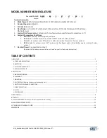
Cold Shot Chillers ACWC-180-EM-DR-LT-0-5 Installation, Operation And Maintenance Instructions Download Page 3

I.


IMPORTANT 

A.


CODES AND REGULATIONS 

The United States Environmental Protection Agency (EPA) has issued various regulations 

regarding the introduction and disposal of refrigerants in this unit. Failure to follow these regulations 

may harm the environment and can lead to the imposition of substantial fines. Because these 

regulations may vary due to the passage of new laws we suggest that, any work on this unit be done 

by a certified technician. Should you have any questions, please contact the local office of the EPA.  

This product is designed and manufactured to permit installation in accordance with National 

Codes. It is the installer’s responsibility to install the product in accordance with National Codes 

and/or prevailing local codes and regulations. The manufacturer assumes no responsibility for 

equipment installed in violation of any codes or regulations. 

IMPORTANT MESSAGE TO OWNER:  

These instructions should be carefully read and kept near the product, for future reference. While 

these instructions are addressed primarily to the installer, useful maintenance information is 

included. To insure proper set up, operation, and performance it is recommended that a licensed 

service professional start this piece of equipment. Have your installer acquaint you with the 

operating characteristics of the product and periodic maintenance requirements. 

B.


INSPECTION 

This product has been inspected at the factory and released to the transportation agency without 

known damage.  Inspect carton’s exterior for evidence of rough handling in shipment.   Carefully 

remove protective wrap and all banding to uncrate, for inspection; if damage is found, report 

immediately to the transportation agency and Cold Shot Chillers.  Provide a report and photographs 

(highly recommended), if possible. 

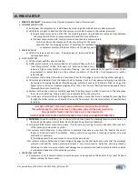
Once it is established that the unit has positive pressure, proceed to installation.  Test the system 

service valves with refrigeration gauges to ensure refrigerant pressure is present and no 

undetectable damage (i.e. dropping the unit) has occurred, when possible. 

C.


SAFETY CONSIDERATIONS 

Installation, start-up, and servicing of this equipment can be hazardous due to system pressures, 

electrical components, and equipment location (roofs, elevated structures, etc.)  Only trained, 

qualified installers and service mechanics should install, start up, and service this equipment.  When 

working on the equipment, observe precautions in the literature, tags, stickers, and labels attached 

to the equipment, and any other safety precautions that apply. 


Follow all safety codes. 


Wear safety glasses and work gloves. 


Use care in handling, rigging, and setting bulky equipment. 


Use care in handling electronic components. 

D.


REPLACEMENT PARTS 


For information on replacement parts, contact Cold Shot Chillers. 


When ordering parts, provide complete model and serial number as shown on the unit nameplate. 


Most parts will be available through local distributors. 


MNL_Standard-Basic_ACWC-24to240-E-(IN PROGRESS)_(0815).docx


- 3 -


Summary of Contents for ACWC-180-EM-DR-LT-0-5

Page 1: ...Houston Texas 77032 Phone 800 473 9178 281 227 8400 Fax 800 473 9175 281 227 8404 www waterchillers com INSTALLATION OPERATION AND MAINTENANCE INSTRUCTIONS ACWC 240 E model shown AIR COOLED WATER CHI...

Page 2: ...ient fan control Casters optional d M20 Suitable for outdoor use to 20 F ambient Hot Gas Bypass and or Wind Baffles may be included Casters optional 7 Electrical Power See specification sheet Variatio...

Page 3: ...has been inspected at the factory and released to the transportation agency without known damage Inspect carton s exterior for evidence of rough handling in shipment Carefully remove protective wrap...

Page 4: ...unit to ensure proper oil return to compressors and fluid draining 2 When unit is in proper location secure unit to foundation or on vibration isolators as needed required by local requirements Fasten...

Page 5: ...efrigerant Charge E ELECTRICAL POWER AND CONNECTIONS1 1 POWER SUPPLY Field wiring must comply with national and local codes a Install a branch circuit fused disconnect of adequate size to handle start...

Page 6: ...ezing can occur from the external ambient or internal system temperatures 2 INTERNAL The evaporator or other heat exchanger is the primary component that is susceptible to freezing even during normal...

Page 7: ...rating of the chiller 2 Some conditions are a Ambient conditions for air cooled systems b Condenser fluid for water cooled systems c Type of fluid being chilled d Design and setup of the chiller e Lea...

Page 8: ...illed with fluid prior to starting e Systems with an open tank are typically capable of bleeding excess air that is returned to the tank when the system is operating Piping in and out are typically be...

Page 9: ...LED readout which is an indication of the current temperature of the fluid in the chiller tank or Leaving Fluid Temperature depending on the specific chiller design 8 COOLING CYCLE Unit is now ready t...

Page 10: ...F At this temperature an internal bi metal disk valve opens and causes the scroll elements to separate which stops compression Suction and discharge pressures balance while the motor continues to run...

Page 11: ...SAFETY LPS a Monitors the pressure of the refrigerant suction line and will automatically open when the pressure drops below the set point and will automatically reset when pressure is above the non a...

Page 12: ...ted valves similar to MCSO however it can be setup to change automatically based on a system safety situation 23 TANK LEVEL OPTIONS a Float Valve a Located inside the tank the float valve is a mechani...

Page 13: ...with wire brush and or abrasive clothes and then the surface can be recoated to reduce future corrosion For severe environments use a durable epoxy paint that can create an oxygen barrier c Fasteners...

Page 14: ...ecome jagged or splattered to avoid premature compressor and or pump failure Contactor points are consumable and their life is dependent on the amount of use and power characteristics at the unit 11 R...

Page 15: ...t unless issue has been resolved Troubleshoot the switch DO NOT BYPASS IMPORTANT This condition can occur when the fluid in the evaporator nears freezing 9 Flow Switch Tripped switch open 9 Determine...

Page 16: ...leak and recharge 4 Overcharged system 4 Remove refrigerant adjust charge FROSTED LIQUID LINE AFTER DRIER 1 Restricted filter drier 1 Remove restriction or replace COMPRESSOR WILL NOT LOAD UNLOAD HOT...

Page 17: ...ply TEMPERATURE CONTROLLER ERROR 1 Temperature indication not accurate 1 Verify temperature sensor is in good condition and mounted properly Adjust the offset Typically it is only adjusted a few degre...

Page 18: ...hnical Specification C Physical Installation Drawings D Electrical Drawings E Component Technical Pump options etc when available F Parts Warranty G Labor Warranty if included H Startup Checklist MNL_...

Page 19: ...r starter or overload or the Tank Level is above the low level if included 2 Any issues with these items will result in a fault There is an initial delay bypassing the flow switch to permit flow to st...

Page 20: ...switch is turned off or a fault occurs DISPLAYS Power ON typical Only at startup Normal display PV b190 DTB series Firmware V1 90 PV 51 3 Present Value SV r r Output type Relay and Relay SV 50 0 Set...

Page 21: ...ow 9600 Leaving Fluid Temperature Too Low Freeze Thermostat is open 9700 Either 1 Pump Safety Circuit has tripped or 2 Low Tank Level at Start 9710 Either 1 Pump Safety circuit was tripped or 2 Low Ta...

Page 22: ...d Rate 9600 LEN Communication Data Length 8 Prty Communication Parity Bit Even StoP Communication Stop Bit 1 Value Set Codes Code Description B ACTUAL SETTINGS r S Operation Mode rUn SP Decimal point...

Page 23: ...PT LIFS 000 100 0 1 2730 Maximilian Drive Houston Texas 77032 Phone 800 473 9178 281 227 8400 Fax 800 473 9175 281 227 8404 www waterchillers com Liquid Flow Switch...

Page 24: ...S Fan Cycling Pressure Switch FST Flow Safety Thermostat FZT Freeze Safety Thermostat GND Ground HG Hot Gas HPS High Pressure Switch L Line LAR Low Ambient Relay LAT Low Ambient Thermostat LFS Liquid...

Page 25: ...in a location away from sources of excessive heat and within the specified ambient operating conditions See Technical Specifications for ambient operating conditions IMPORTANT Use this P266 Single Ph...

Page 26: ...ctronic Pressure Transducer 0 to 52 bar 0 to 754 psi total range with a 1 4 in SAE Female Flare connection and a 2 meter 3 1 ft cable P266xxx x Product P266xxx x Single Phase Condenser Fan Speed Contr...

Page 27: ...alves filter drier pump down valves fan cycling head pressure controls Process Fluid Components Bronze Y strainer with 20 mesh stainless steel screen Pumps are stainless steel centrifugal Tanks are in...

Page 28: ...0 0_ 0414 doc PUOD 240 003 0 0 3 Hp 3 Motor ODP Pump with 5 5 Impeller and 0 250 Vane at 3500rpm ASP SSPC Pump Motor Assembly Exploded View If needed the pump label is located on the pump casing near...

Page 29: ...orts Condensing Area Access Panel Line Voltage Temperature Controller Control Panel PUMP COOL OFF Power Switch High Pressure Reset NOTES Unit should be installed with at least 4 clearance on all sides...

Page 30: ...it System 2 3 5 2015 SCALE NTS DWG_RefrigerantCircuit Ref Chw ACWC SingleCircuit Typical_0215 vsd SHEET 1 NOTES All specifications and designs are subject to change without notice Hot Gas Bypass optio...

Page 31: ...SHEET 2 CHILLER PUMP WATER SUPPLY OUT MANUAL BYPASS STAINLESS STEEL TANK WITH SHOE BOX LID WATER RETURN IN DRAIN STAINLESS STEEL COPPER BRAZED PLATE EVAPORATOR TEMPERATURE SENSOR Temperature Controlle...

Page 32: ...mp PLC Programmable Logic Controller PS Power Supply RC Run Capacitor SW1 Selector Switch Pump Off Cooling SW2 Selector Switch Process Pump SW3 Local Remote Switch TB1 Terminal Block 1 for Internal TB...

Page 33: ...PLC INPUTS PLC OUTPUTS RED BLK TRAN1 PS 24VDC HPS VIO GRA YLW X1 X0 X2 S S WHT SW1 1 SW1 2 BRN BLU ORN GRN X3 X4 X5 X7 X6 BLK BLK PAGE NOTES 1 Control transformers must be wired tapped for the approp...

Page 34: ...ontrol with External Supplied Control Voltage 1 2 33 32 OPTION CODE VARIATIONS RS Remote System ON OFF Control with internal supplied 24VDC requiring Dry Contacts RS V Remote System ON OFF Control wit...

Page 35: ...Notes...

Page 36: ...MAINTENANCE RECORD DATE PROCEDURE PERFORMED...

Page 37: ...ll piping is connected properly as appropriate Yes No 12 All chilled water valves are open as appropriate Yes No 13 Crankcase heaters energized for 24 hours before start up Yes No 14 Outdoor piping wr...

Page 38: ...__________________________________________________________________ __________________________________________________________________________________________________ __________________________________...

Page 39: ...ight charges to ship these parts EXCLUSIONS The foregoing provisions state the exclusive remedy for any breach of warranty or any other claim in respect to the product described on the reverse side of...

Page 40: ...s that are not manufacturing defects and are therefore not included in this Limited Warranty 1 Damage to unit or unsatisfactory operation due to improper cleaning or use of unit in corrosive atmospher...

Reviews: