


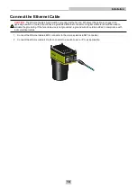


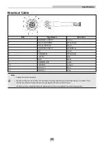


Connect the Breakout Cable
CAUTION
:
To reduce emissions, connect the far end of the Breakout cable shield to frame ground.
Note
:
l
Perform wiring or adjustments to I/O devices when the vision system is not receiving power.
l
Exposed wires can be cut short or wire ends trimmed, and the wires tied back using a tie made of non-
conductive material. Keep all bare wires separated from the +24VDC wire.
1. Verify that the 24VDC power supply being used is unplugged and not receiving power.
2. Optionally, connect the I/O wires to an appropriate device (for example, a PLC, encoder or serial device). For
more information, refer to
.
3. Attach the Breakout cable's +24VDC (Red wire) and GND (Black wire) to the corresponding terminals on the
power supply.
CAUTION
:
Never connect voltages other than 24VDC. Always observe the polarity shown.
4. Connect the Breakout cable's M12 connector to the vision system's PWR connector.
5. Restore power to the 24VDC power supply and turn it on if necessary.
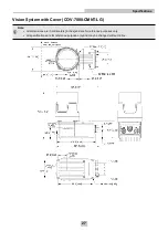
15
Installation


