Code Blue
•
259 Hedcor Street
•
Holland, MI 49423 USA
•
800.205.7186
•
www.codeblue.com
GU-156-I
page 18 of 26
CB 6 Series
Administrator Guide
13 WM-180 Wall Mount Installation Instructions
Note:
If WM-180 unit does not include an IP or Analog controller board, then it must be located near
an IA4100 or IP5000 speakerphone for the 20’ supplied PAS cables to reach it.
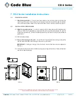
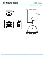
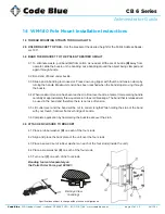
See included drawing for anchor bolt and conduit locations.
WITH CONTROLLER BOARD
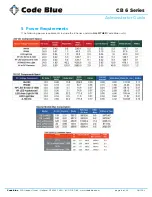
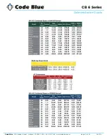
Supply 24V AC to Power Manifold.
Supply Phone line to Phone Port if analog controller board, or Ethernet IP Connection to LAN port if
IP Controller board.
Reference
IA4100 Admin and User Guide
for programming of analog controller board.
Reference
IP5000 Admin and User Guide
for programming of IP controller board.
Code Blue Guides
are located at
www.codeblue.com > support > downloads.
WITHOUT CONTROLLER BOARD
Supply 24V AC to Power Manifold
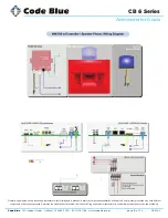
See attached Wiring Diagram for connecting, PAS Audio Cable and the PAS Control Cable, to the
nearby IA4100 or IP5000 speakerphone.
Reference
IA4100 Admin and User Guide
for programming of analog controller board.
Reference
IP5000 Admin and User Guide
for programming of IP controller board.
Code Blue Guides
are located at
www.codeblue.com > support > downloads.
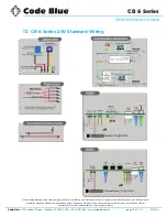
See diagrams next page

