


6
2009 Audiovox Electronics Corporation. All rights reserved.
5
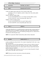
RED
BATTERY 12V ( + )
Locate 1 of the vehicle’s constant 12 Volt battery wires at the ignition switch.
Verification: This wire will register ( + ) voltage in all positions of the ignition
switch.
Connect the RED wire to the constant 12 Volt battery wire.
NOTE: Remove all fuses until all connections are made.
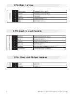
6 Pin Input / Output Harness
1
PURPLE
DOOR TRIGGER INPUT ( + )
Locate the vehicle’s dome light or door pin switch wire.
Verification: This wire will register positive voltage (POS) when the door is
opened and the interior light is on. This wire will
register ground or "0" Volts when the door is closed and the interior light is
off.
Connect the PURPLE wire to the vehicle’s positive door input wire(s).
NOTE: Certain vehicles may require multiple connections. Refer to vehicle
application guide
2
BLUE
TRUNK PIN INPUT ( - )
Locate the vehicle’s trunk pin switch wire and connect to the BLUE wire.
Verification: This wire when connected will register ground when the
vehicle's trunk is opened.
Connect the BLUE wire to the trunk pin.