14
10/C Active Output (20 AWG -) (BLUE/BLACK)
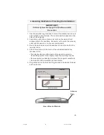
Connect the 10/C wire to add-on relays as described in Diagram
14, or to an optional component requiring a ground signal when
the vehicle is running via remote start.
Note:
If you are connecting the 10/C wire to more than one relay,
install 1-amp blocking diodes (1N4001 or equivalent) as shown in
the Diagram 14.
Interrupting a Sensor or Component while the Vehicle is running
via Remote Start
Use an SPDT relay (not supplied) and connect as shown in
Diagram 15.
3. Car Start Harness (C),
cont’d
10/C WIRE
To Alarm
From Sensor
Constant 12V+
Cut Here
Sensor Trigger Wire
Diagram 15
Install Diodes Here
Diode stripe should
face toward module
10/C WIRE
Diagram 14
630.p65
10/17/03, 7:29 PM
14


