background image

FIGURE 1

7.00"

6.25"

NOTE :  All of the information listed in this booklet
must be given to the end user by the installer.

1 )  Cut a hole in the desired mounting location to

the dimensions shown in Figure 1.  Make sure
this hole is properly oriented to a structural
member of the vehicle for a secure mounting.
This installation may require the use of spac-
ers or longer mounting screws to bring the
product to the desired orientation with the
exterior surface.  In some installations it may
be necessary to fabricate a special adaptor
plate to achieve the desired position on the
vehicle.

2 ) Hold speaker assemblies against the bumper

and inscribe locations for drilling holes for the
mounting screws.

4

3 ) At the inscribed positions, drill holes for the

provided 1/4" x 2-1/2"  screws using a 9/32"
drill bit.

4 ) Attach the speaker assemblies and bezel to

the vehicle using the fasteners shown in
Figure 2.  Make sure that the siren wires are
clear of the mounting bracket to avoid dam-
age during installation.  In addition, DO NOT
TIGHTEN  
the mounting screws completely
until the speaker is parallel and evenly
positioned with the holes on the vehicles
exterior.

5 ) Connect the wires from the speaker assem-

bly to the leads coming from the siren control
h e a d .
NOTE:  When two or more speakers are to
be operated by the same control head, the
speakers must be connected in phase.  In
order to accomplish this, the white wires,
which are connected to the number 1 termi-
nals on the siren drivers, must be connected
together to the same output terminal on the
siren amplifier.  Likewise, the blue wires,
which are connected to the number 2 termi-
nals on the drivers, must be connected
together on the other output terminal of the
siren amplifier.

FIGURE 2

Cleaning

Clean with soap and water to remove all salt, dirt or mud.  Do not use any abrasive cleaners or harsh chemi-
cals because the protective coating on the aluminum may be damaged allowing the exposed aluminum to dull
in appearance or corrode.

Maintenance

Maintenance of your FM100C and FM100V involves the cleaning of the unit and in some cases the replace-
ment of the siren driver, if required.

2

1

Summary of Contents for FM100C

Page 1: ...equipment INSTALLATION OPERATION MANUAL MODEL FM100C OR FM100V Patent Pending SPEAKER FLUSHMOUNT Contents Introduction 2 Unpacking Pre Installation 3 Installation Mounting 3 Maintenance 4 Cleaning 4 Changing Drivers 5 Troubleshooting 5 Parts List Replacement Parts Exploded View 6 Warranty Product Returns 7 IMPORTANT Model FM100 ...

Page 2: ...cy warning signal Never take the right of way for granted It is your responsibility to be sure you can proceed safely before entering an intersection driving against traffic responding at a high rate of speed or walking on or around traffic lanes The effectiveness of this warning device is highly dependent upon correct mounting and wiring Read and follow the manufacturer s instructions before inst...

Page 3: ...rrier immediately 3 Installation and Mounting WARNING Larger wires and tight connections will provide longer service life for components For high current wires it is highly recommended that terminal blocks or soldered connections be used with shrink tubing to protect the connections Do not use insulation displacement connectors e g 3M Scotchlock type connectors Route wiring using grommets and seal...

Page 4: ...void dam age during installation In addition DO NOT TIGHTEN the mounting screws completely until the speaker is parallel and evenly positioned with the holes on the vehicles exterior 5 Connect the wires from the speaker assem bly to the leads coming from the siren control head NOTE When two or more speakers are to be operated by the same control head the speakers must be connected in phase In orde...

Page 5: ... in the installation and mounting section in this booklet Make sure the wires are tightly sealed at all exit points from the speaker assembly Fill any voids with silicone caulking NOTE When reassembling the speaker make sure to align the drain holes on the driver driver cover and driver cap the drain hole on the Atlas driver is located behind a metal tag These holes should be oriented to the base ...

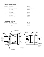
Page 6: ...of speaker bracket Parts Exploded Views Parts Shown in Fig 2 1 Coated Mounting Bracket S35470 2 Trim Bezel T03776 Ref Number Description Part No 3 Speaker wire Assemblies T04346 T04347 4 Speaker Screws T06519 5 Speaker Horn S85477 6 Driver Cover T03739 7 100w Siren Driver T03470 8 Driver Cap S85478 9 Nose Cone Screw T09204 Ref Number Description Part No Self Tapping Thread Clearing ...

Page 7: ...NOTES ...

Page 8: ...appropriate or inadequate wiring or circuit protection causes this warranty to become void Failure or destruction of the product resulting from abuse or unusual use and or accidents is not covered by this warranty PSE shall in no way be liable for other damages including consequential indirect or special damages whether loss is due to negligence or breach of warranty PSE MAKES NO OTHER EXPRESS OR ...

Reviews: