background image

Nothing 

Comes Close to a Cobra

®

19

decreasing the STC value to SHORT in shallow waters or to switch it to VERY
SHORT or OFF.

4.8.2

Auto range fails, and the digital depth readout displays a
very shallow reading. What should I do?

This usually happens if the STC is off or is set to a low value causing disturbs
from surface clutter to be stronger than bottom echoes. Try increasing the
STC value.  As general rule STC has to be set as in shallow waters and
LONG in depth waters.

4.8.3

Auto-range fails in very deep waters displaying a digital
very shallow depth readout. What should I do?

The Fish Finder capability to detect the bottom decreases as the bottom depth
increase. If the bottom composition is soft as mud, if the sea conditions are
bad, if there are thermoclines or the water is full of materials in suspension it
can further decrease thus causing the digital depth readout to fail. When this
happens the auto-range algorithm also fails. To recover from this situation it is
necessary to switch to manual range mode and to set the manual depth
mode. When manual depth mode is selected the algorithm that calculates the
digital depth readout searches for the bottom within the range manually
selected by the user. At this point it is necessary to increase manually the
range until the bottom becomes graphically visible. If the echoes from the
bottom are strong enought, the Fish Finder shall look to the bottom giving a
correct depth reading and shall be possible to return in auto range mode.
Please note that if one or more of the conditions that reduce the echoes from
the bottom listed above is true the bottom may be not visible at all, in this
situation a strong thermocline or surface clutter may be interpreted by the Fish
Finder as the bottom.

4.9

At a very shallow range upper half of the screen appears
almost completely filled by the surface clutter. How can I
eliminate it?

This is normal in shallow waters. To clean up the surface clutter without
degrading the digital depth readout algorithm functionality it is possible to set
the STC value  to custom setting the STC lenght to the same size of the
surface clutter, and increasing the STC strenght until the  image on the screen
cleans up. Please note that in very shallow waters it is usually better to switch
to manual gain mode to reduce gain fluctuation due to rapidly changing
bottom conditions.

Frequently Asked Questions

Summary of Contents for Marine MF2500

Page 1: ......

Page 2: ...nTM 2006 Cobra Electronics Europe Limited 6500 West Cortland Street Chicago Dungar House NorthumberlandAvenue Dun Laoghaire Illinois 60707 USA County Dublin Ireland Cobra NightWatch Nothing Comes Clos...

Page 3: ...ION Should you encounter any problems with this product or not understand its many features please refer to this Owner s Manual If you require further assistance after reading this Owner s Manual Cobr...

Page 4: ...CobraMarineTM dealer or distributor Extensive exposure to heat may result in damage to the MF 2500 Fish Finder Connection to the power source with reversed polarity will damage the MF 2500 Fish Finde...

Page 5: ...arineTM Series chartplotter WHAT IS IN THE BOX When the package containing the MF 2500 Fish Finder is first opened please check it for the following contents if any parts are missing contact the deale...

Page 6: ...WHAT IS IN THE BOX 4 1 MANUAL ORGANIZATION 5 1 1 TABLE OF CONTENTS 5 1 2 OVERVIEW 6 2 THE MF 2500 FISH FINDER 7 2 1 TECHNICAL SPECIFICATIONS 7 2 2 DIMENSIONS 8 2 3 MOUNTING THE FISH FINDER 8 2 3 1 Ins...

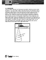
Page 7: ...strike fish structures thermoclines temperature changes in the water etc When the wave strikes an object s a certain amount of the wave is reflected back to the transducer depending on the composition...

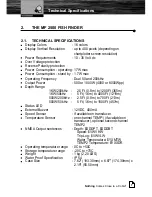
Page 8: ...4000 or 8000Wpp Depth Range 1KW 200kHz 2 5 Ft 0 8m to 1200Ft 365m 1KW 50kHz 5 Ft 1 6m to 4000Ft 1219m 500W 200kHz 2 5 Ft 0 8m to 700Ft 213m 500W 50kHz 5 Ft 1 6m to 1500Ft 457m Status LED External Buz...

Page 9: ...ons 2 2 DIMENSIONS 2 3 MOUNTING THE FISH FINDER The MF 2500 Fish Finder should be preferabily mounted in a dry and well ventilated location Do not mount it where it will be submerged in liquids or exp...

Page 10: ...g to the instructions provided with it Connect the POWER cable to the battery Please be advised that the MF 2500 Fish Finder when not operating will remain in Stand By mode 2 3 2 Installing Optional D...

Page 11: ...e sentences 4 NORMAL FISH FINDER MODE LED Behavior 1 short flash every 2 seconds The MF 2500 Fish Finder and the transducer are operating properly This is the normal behavior when everything is workin...

Page 12: ...Nothing Comes Close to a Cobra 11 External Connections 2 5 EXTERNAL CONNECTIONS...

Page 13: ...to the MF 2500 Fish Finder The MF 2500 Fish Finder is active sending the digital depth through the NMEA interface even when the power chartplotter is turned off thus the need for a switch In the examp...

Page 14: ...Nothing Comes Close to a Cobra 13 Chartplotter Connection Diagram 2 7 CHARTPLOTTER CONNECTION DIAGRAM See the following picture to make the connection to the chartplotter...

Page 15: ...ice that transmits and receives sound waves into the water The active component inside the transducer is commonly referred to as an element but actually is a piezoelectric ceramic material CobraMarine...

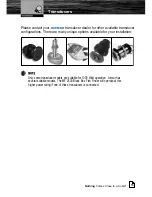
Page 16: ...transducer configurations There are many unique options available for your installation Only some transducer models are suitable for 1000 Watt operation Airmar has several suitable models The MF 2500...

Page 17: ...ables from the MF 2500 Fish Finder in case I need to do so for the installation Open the MF 2500 Fish Finder box unscrewing the four screws see the following figure Once the screws are removed pull ou...

Page 18: ...cruising it is possible to select the CRUISE preset 4 3 What are preset modes Preset modes are pre defined settings of the Fish Finder operating parameters There are five preset You can use them to qu...

Page 19: ...4 6 Can I always leave the Fish Finder in Full Auto auto gain and auto range mode Yes but note that the full auto mode suits the 90 of the cases however in extreme situations the auto modes may fail a...

Page 20: ...orithm that calculates the digital depth readout searches for the bottom within the range manually selected by the user At this point it is necessary to increase manually the range until the bottom be...

Page 21: ...mall targets what shall I do to reduce the screen clutter Try increasing the NOISE LEVEL or decreasing the GAIN OFFSET 4 13 In very shallow waters when the AUTO GAIN mode is selected there are fluctua...

Page 22: ...tallation 9 L LED 9 N NMEA Output sentences 7 O Operating Frequency 7 Operating temperature range 7 Output Power 7 Over Voltage protection 7 OVERVIEW 6 P package 4 Power Consumption 7 Power Requiremen...

Page 23: ......
Reviews: