COBHAM D-MBR 3707 User Manual Download Page 68

D-MBR 3707-3708 PS NFPA CLASS A SIGNAL BOOSTER


PRODUCT DESCRIPTION AND USER’S MANUAL 

www.cobham.com/wireless


Date: 17-Jan-16 

Cobham Wireless 


Coverage


Page | 60


Rev. 1.1 

Doc. No.00060CDUM 


6.4  CMU Software Upgrade 

NOTE: This procedure is performed for every new management version. 
The procedure described in this section is used to upgrade the Booster  software. The CMU  SW 
upgrade procedure consists of loading the new software version and installing it in the CCD. The 
CMU can store two versions on two separate data banks enabling restore to a previous version.  

To Upgrade the CMU SW 

1.  In the left pane, click the CMU item and then click the CMU SW Upgrade tab. The following 

screen appears (the Browse field will be empty). 


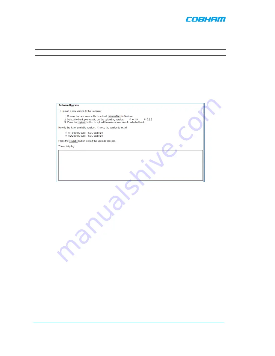
Figure  6-10. CMU Upgrade 

2.  Choose and save the file onto the Booster: 


(1)  Click Choose File to search for the location and choose the new software file. It 
will be displayed adjacent to the Choose File button. 


(2)  Select the bank where the file will be stored. (Before it is populated the bank will 
be named ‘empty slot’. After it is populated, it will take on the name of the stored 
software version). Any existing software file will be replaced. 


(3)  Press Upload to save the file to the selected bank (slot). The available software 
files to choose from will be listed. 

3.  Choose the required software file and click Install.  
4.  The Activity Log will indicate status and upgrade completion 


Summary of Contents for D-MBR 3707

Page 1: ...ortant thing we build is trust D MBR 3707 3708 Class A PS NFPA Signal Booster The future of in building coverage User Manual 00068CDUM Rev 1 2 This manual is relevant for 700 800 MHz Digital Multi Cha...

Page 2: ...ossible from the user s viewpoint Please submit your comments to the nearest Cobham Wireless sales representative Contact Information Headquarters Axell Wireless trading as Cobham Wireless Aerial Hous...

Page 3: ...ded The safety warnings in the form of Dangers Warnings and Cautions must be followed at all times These warnings are flagged by the use of a warning icon usually the triangular alert icon seen below...

Page 4: ...rking with un insulated wires or terminals Caution Safety to personnel Before installing or replacing any of the equipment the entire manual should be read and understood The user needs to supply the...

Page 5: ...used in accordance with the instruction manual may cause harmful interference to radio communications Operation of this equipment in a residential area is likely to cause harmful interference in which...

Page 6: ...t should be installed and operated with minimum distance 28 cm between the antenna and your body Conform ment la r glementation d Industrie Canada le pr sent metteur radio peut fonctionner avec une an...

Page 7: ...vironment 10 2 4 2 Verifying the Link between the BTS and the Signal Booster 11 2 5 RF Cable Installation Guidelines 12 3 BOOSTER MOUNTING AND INSTALLATION 13 3 1 Booster Installation Overview 13 3 2...

Page 8: ...5 7 Changing Password 52 6 ADMINISTRATIVE OPERATIONS 53 6 1 User Management 53 6 1 1 User Levels 53 6 1 2 Viewing the List of Defined Users 53 6 1 3 Adding Users 54 6 1 4 Editing a User 54 6 1 5 Dele...

Page 9: ...mechanism will be triggered The signal booster protects against degradation of the system s sensitivity and coverage This is implemented by the inbuilt AGC per channel filter feature which permits equ...

Page 10: ...e Protection Association NFPA requirements power to the Signal booster is provided via an uninterrupted power source This can either be a UPS or if a UPS is not available an AC Feeder and Battery Char...

Page 11: ...Signal Booster RF Gain to the desired value Note To reset the Signal Booster to its highest set gain value disconnect the Signal Booster power cable for several seconds and re connect 1 5 Power Feeder...

Page 12: ...ause damage to the signal booster due to over heating Figure 1 3 D MBR Front Panel Interface Description BASE Donor antenna connections See section 2 1 MOBILE Service antenna connections See section 2...

Page 13: ...own converted and amplified The signals are then forwarded to the service antenna In the uplink the process is reversed The maximum Analog Gain is 95dB where Channel Gain between 0dB and 95dB is achie...

Page 14: ...nnecting the Donor antenna to the Signal Booster and the attenuation 2 1 2 Donor Antenna specifications Yagi type or similar 10 to 15 dBi gain very sharp beam pointed to the BTS Cable and jumper loss...

Page 15: ...ing the Service antenna to the Signal Booster and the attenuation 2 2 2 Indoor Installations 2 2 2 1 Recommended Antennas The following describes the requirements for an omni directional mobile used f...

Page 16: ...ations in which the Mobile antenna is installed outdoors the antenna type is chosen according to the available infrastructure single pole or horizontal installation In addition isolation between the d...

Page 17: ...ntenna on a COMMON tower It is required to set the distance between them to achieve maximum isolation The figures below illustrate the installations Figure 2 1 Service above Donor Antenna Figure 2 2 D...

Page 18: ...th the Uplink and Downlink bands 4 Register the lower result for system operation 2 3 Required BTS Information Required BTS Information BTS channels BTS output power per channel BTS antenna gain BTS a...

Page 19: ...analyzer measure the received signal from BTS at the Donor antenna port near the Signal Booster 2 Adjust the Donor antenna direction to receive the maximum signal strength 3 Compare the received sign...

Page 20: ...igh performance flexible low loss 50 ohm coaxial communications cable All cables shall be weather resistant type If the coaxial cables are NOT weather resistant type wrap the exterior coaxial cables w...

Page 21: ...arger is installed adjacent to the Booster Refer to chapter 4 for instructions on installing the Battery Charger WARNINGS Follow all local safety regulations when installing the Signal Booster and Cha...

Page 22: ...acking the unit 2 Perform a visual inspection to reveal any physical damage to the equipment 3 Verify that all of the items listed in the packing list are included Otherwise contact yourCobham Wireles...

Page 23: ...onnection cable clearances the connections located on the underside of the unit will need at least 300mm vertical clearance below the unit to enable the connections to be made The minimum bend radius...

Page 24: ...mount the unit The signal booster must always be installed vertically with the connectors on the underside for protection Horizontal installation on a bench for long time may cause damage to the sign...

Page 25: ...vertically with the connectors on the underside for protection Horizontal installation on a bench for long time may cause damage to the signal booster due to over heating 3 3 3 1 Wallmount Bracket Ass...

Page 26: ...pipe and cable detectors are available for this type of inspection The Repeater wall mount brackets assembly should be fixed to a solid wall these include brickwork block work and concrete To provide...

Page 27: ...les to protect your eyes from flying debris when using power tools 3 Hold the drill bit against the mark and begin drilling slowly so that the bit does not wander from the position The wall should be...

Page 28: ...recommended that two people lift the repeater since depending upon the configuration the idRU weighs between 20 and 38 kg 44 and 84 lb To mount the Unit Align repeater with the four fixings Great care...

Page 29: ...precautionary measure it is recommended to further secure the Booster to the wall in addition to the bracket This can be done using any appropriate method It is the installer s responsibility to ensu...

Page 30: ...Wireless Coverage Page 22 Rev 1 1 Doc No 00060CDUM Another example is of a unit installed on a stadium gantry Again the support can be in the form of a cable harness loop using the handle of the unit...

Page 31: ...ical for both BOOSTER and BATTERY CHARGER 3 4 1 1 Grounding Wire Requirements Requirements for grounding wires Protective grounding conductor should be aluminum with cross section 10AWG Lug of the pro...

Page 32: ...k between BTS and donor antenna RF cable installation guidelines Connecting the antennas CAUTION Do not connect the antenna cables to the Signal Booster before verifying the installation parameters sp...

Page 33: ...ns with UPS refer to your UPS manual for instructions on dry contact alarm connections to the Fire Department Control box Note the following The alarms can be connected any time before or after the sy...

Page 34: ...e dry contact alarm output and then configuring EXT Alarm IN 1 as Normal High according to section 5 5 Figure 3 18 D MBR Alarm Connector Pinout Pin No Signal Name Wire Colour 1 External Alarm 1 Black...

Page 35: ...rce before working with uninsulated wires or terminals The Signal Booster operates from a 48VDC power source either UPS or Battery Charger ordered separately NOTE The AC Feeder Battery Charger install...

Page 36: ...izing an external customer purchased battery for backup in case power failure NOTE Use only external batteries meeting the specifications given in section 4 4 6 This section describes the Battery Char...

Page 37: ...are connected to the Fire Department Control Box AC Input Fail Low Battery capacity Charge Fail As long as the AC power source is available the Charger provides 32 to 72 VDC to the booster and maintai...

Page 38: ...connection BATTERY Connection to external re chargeable 200H battery 4 4 6 for external battery requirements Charging time for full 200AH battery estimated to about 20hrs ALARMS Three Dry contact alar...

Page 39: ...the Charger providing a load BEFORE AC feed or the Battery is connected to the charger BEFORE POWERING THE SYSTEM on make sure CHARGER DC OUT is connected to BOOSTER DC IN BATTERY connection at CHARGE...

Page 40: ...Booster perform the following 1 Examine the shipping container for damage before unpacking the unit 2 Perform a visual inspection to reveal any physical damage to the equipment 3 Verify that all of t...

Page 41: ...4 4 3 Charger Mounting Procedure The charger is mounted next to the Booster and the mounting instructions are identical to that of the Booster Refer to section 3 3 for mounting instructions 4 4 4 Char...

Page 42: ...at are connected to the Fire Department Control Box AC Input Fail Low Battery Capacity Charge Fail NOTE AC Input Fail can also be connected to the Booster External Alarm connector Figure 4 6 Charger C...

Page 43: ...can be provided for ONE of these alarms This is done by connecting the alarm to the Booster External Alarm Connector Ext Alarm IN 1 section 3 4 3 3 It is then required to configure External Alarms 1 a...

Page 44: ...e Charger to the battery Be sure to connect according to the following connection sequence otherwise the Battery Charger may be damaged a ALWAYS first connect Charger to Repeater b Connect Charger to...

Page 45: ...f this section Be sure AC power feed to the Charger is DISCONNECTED before connecting or disconnecting the Charger to the battery Figure 4 9 Battery Charger to Booster Power Connections 3 Connect the...

Page 46: ...procedures for the D MBR Booster 5 1 Overview of the Commissioning Procedure The Booster is designed for simple plug and play operation only requiring the setup of a number of parameters via a local W...

Page 47: ...to the booster 1 Connect to the Boosters front panel Ethernet port using the supplied Ethernet cable Figure 5 2 Local Setup Connection 2 Verify the setup computer s NETWORK PARAMETERS are in the same...

Page 48: ...describing the application window and then proceed to configure the signal levels according to section 5 3 Figure 5 5 Login 5 2 2 Navigating the Web GUI Application This section describes how to navig...

Page 49: ...the Web Access application in case of failure or display issues Date and Time Access Booster Date and Time settings User Currently logged in authentication level and user Logout Click to logout curren...

Page 50: ...ic information including filter width etc See section 6 2 2 Backup and Restore Used to backup and manage band level configuration files See section 6 3 5 2 2 4 CMU Pane and Tabs This section describes...

Page 51: ...in this section The defined filters are graphically displayed in the lower part of the screen To configure the signal level and channels 1 In the left pane click the 700 800 item 2 View the valid filt...

Page 52: ...composite output power exceeds the defined value the Smart ALC feature begins working refer to section 1 4 for more information on SALC Set Max Composite UL Output Power set according to your site re...

Page 53: ...d calculated input power and isolation measurements Recommended Maximum Gain setting is approximately 16 dB less than the isolation between the service and donor antennas More information on Downlink...

Page 54: ...te 17 Jan 16 Cobham Wireless Coverage Page 46 Rev 1 1 Doc No 00060CDUM 10 After the channels have been configured and the required coverage is attained for the location verify that no Alarms are gener...

Page 55: ...on the unit since this provides the timestamp for each logged event and alarm This operation requires resetting the Booster To set the Boosters date and time 1 Click on Date Time in the Operations Ite...

Page 56: ...he CMU option and select the External Alarms tab The following dialog appears Figure 5 15 External Alarm Configuration Dialog 2 Set Alarm 1 EXT 1 Normal mode as follows If an external alarm from the B...

Page 57: ...gure the IP Address and SNMP Notifications 1 Click on CMU in the left pane and select the Communication Configuration tab The following screen appears Figure 5 16 Communication Configuration Dialog Th...

Page 58: ...er to the system The default Static IP address is 192 168 1 253 It is highly recommended to preserve this setup In case of a change make sure you record the newly assign IP To configure the Booster IP...

Page 59: ...on 3 In the Use Destination field select the SNMP option 4 For each destination Define the IP Address where the IP addresses should be in the same subnet as the booster Define the Community names defa...

Page 60: ...or security it is recommended to change the password of the Administrator To change the administrator password 1 From the left pane select Users The list of users is displayed in the User s Pane 2 In...

Page 61: ...existing users 6 1 1 User Levels Two user levels are available Admin has access to all administration and configuration options including user management Default Password admin and default User Name...

Page 62: ...er 5 Select the User Role access level This defines the operations that the user will be able to perform 6 Enter the Password and in Verify Password enter the password again for verification 7 Click O...

Page 63: ...via the Band Info tab 6 2 1 Viewing Booster Level Information Use the CMU Info screen to view the hardware and software versions of the Booster and to assign the Booster a recognizable name To access...

Page 64: ...lays general identification information such as build version valid filter definitions and more To access the Booster Information window 1 From the left pane select the 700 800 item 2 Select the Band...

Page 65: ...click the Backup Restore tab The following screen appears Figure 6 5 Backup and Restore The file management buttons provide the following options Item Description Backup Backup the currently running c...

Page 66: ...be added to the table displayed in the Backup Restore tab Note The file name under File is a link that enables uploading the file to another location Figure 6 6 Backup Booster Info 6 3 3 Restoring Ba...

Page 67: ...6 8 Upload Configuration File 2 Click the Upload button 3 Select the file from the Browse dialog and click Open 4 The file will be listed in the Backup Restore table 6 3 5 Saving Configuration File t...

Page 68: ...pane click the CMU item and then click the CMU SW Upgrade tab The following screen appears the Browse field will be empty Figure 6 10 CMU Upgrade 2 Choose and save the file onto the Booster 1 Click C...

Page 69: ...rms 7 1 LED Troubleshooting Two status LEDs are located on the Booster panel one for the Uplink and one for the Downlink The LEDs provides the following information Color Description Corrective Action...

Page 70: ...g screen This screen provides an analysis tool to get information of any event that has occurred its originator when if they return and their type NOTE Time of occurrence of the events is set accordin...

Page 71: ...17 Jan 16 www cobham com wireless Doc No 00060CDUM Rev 1 1 Page 63 7 3 Viewing Activated Alarms Click on CMU in the left pane and select the CMU Alarms tab The following screen appears The screen show...

Page 72: ...NOTE The alarm settings can be modified via the Alarms Configuration tab See the following page for alarm descriptions NOTE Use the ACK ALL button to reset ALL displayed alarms Alarm Fault and most pr...

Page 73: ...nal level of the Donor Base antenna If the alarm is still raised then you can raise the value of the DL Output Threshold Delta dBm as needed PAmp Current Description Power Amplifier current is not wit...

Page 74: ...odify the factory set level minor major or critical of specific alarms when they are activated To modify the Alarm Severities From the left pane select 700 800 item and choose the Alarms Configuration...

Page 75: ...Hz 37 dBm 28 dBm Composite Output Power SMR 800MHz 37 dBm 28 dBm Noise Figure Maximum Gain 5 0 dB General Dimensions W x D x H 21 3 x 15 x 12 3 inches 540 x 382 x 313 mm Power Supply 36 76 VDC Power C...

Reviews: