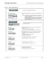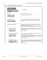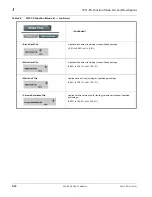
9921-FS-OM (V1.18)
9921-FS PRODUCT MANUAL
2-17
Installation and Setup
Setting Up 9921-FS Network Remote Control
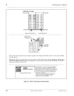
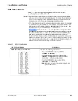
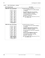
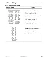
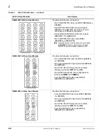
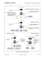
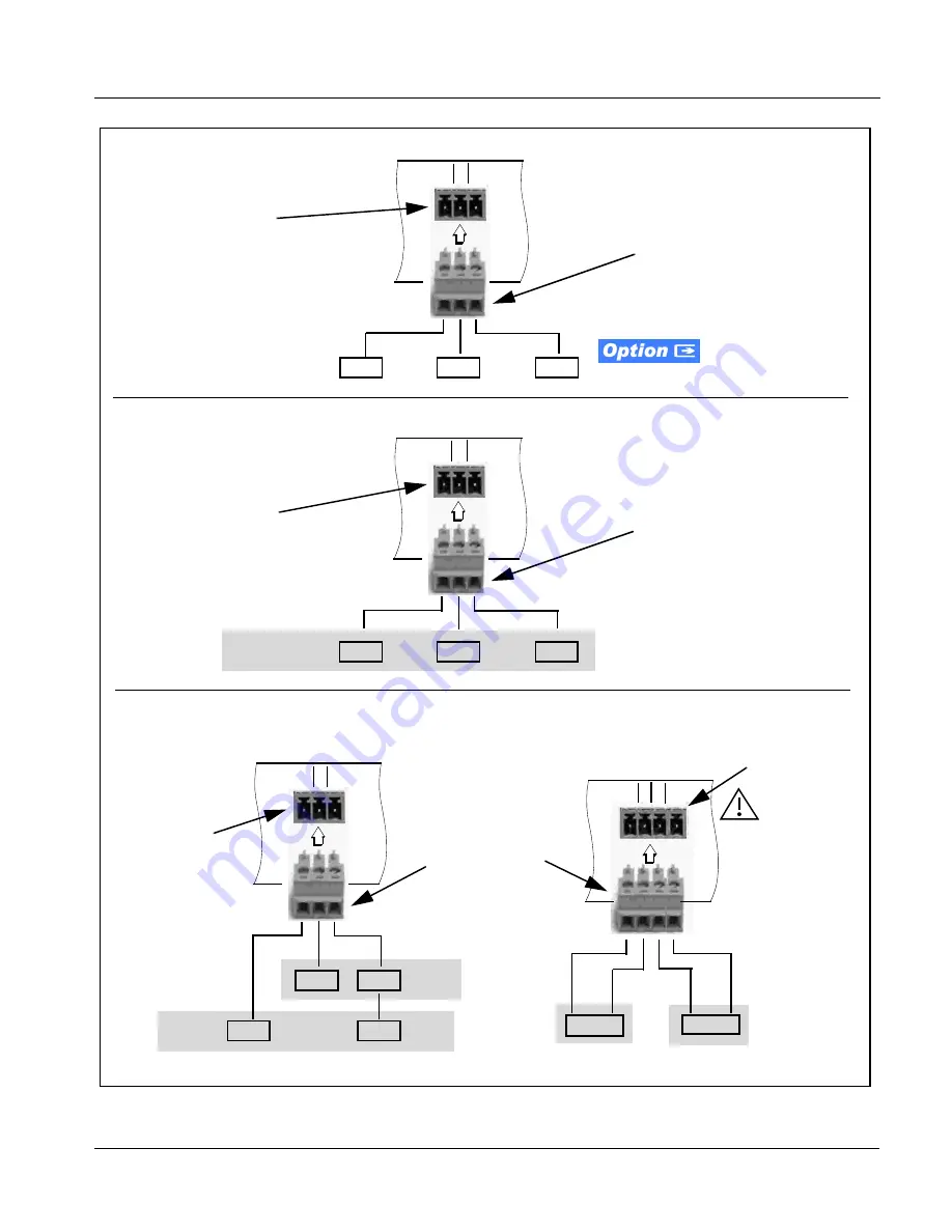
Figure 2-4 Phoenix Terminal Connections
+
–
G
Removable Phoenix plug view oriented
with top (screw terminals) up
Note: Unbalanced connections can be
connected across the + and G
terminals. Note that this connection
will experience a 6 dB voltage gain
loss. Adjust input gain for these
connections accordingly.
Rear module
PCB connector
+ - G
A (-)
B (+)
G
RS-485
Removable Phoenix plug view oriented
with top (screw terminals) up
Note: RS-485 communication will not work if
any of the connections are reversed from
that shown here.
Rear module
PCB connector
2 1 C
IN 2
G
IN 1
G
GPI 2
GPI 1
Removable Phoenix
plug view oriented
with top (screw
terminals) up
Rear module
PCB connector
1 2 G
Balanced Analog Audio Port Connections
COMM Port Connections
GP0 Port Connections
GPO 1
Rear module
PCB connector
C 1 2 C
GPO 2
GPO controlled circuit
must not exceed
voltage/current ratings.
See Technical
Specifications (p. 1-28)
in Chapter 1,
Introduction.
GPI Port Connections

