


18 •
Important: Always read and follow the on-screen operating instructions.
V
Viid
de
eo
o B
Ba
alla
an
nc
ce
er
r
M
Ma
at
tc
ch
hiin
ng
g
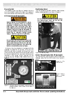
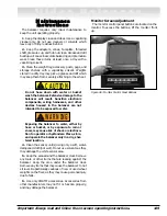
A matching procedure may involve the loos-
ening of tire beads and the inflation of a tire.
Training is necessary in tire changer opera-
tion and understanding the dangers
involved during bead seating and tire infla-
tion before attempting this stage of a
matching procedure. Read the operators
manual supplied with the tire changer and
consult a supervisor.
Typically, if the static limit unbalance is exceeded, the
operator will choose Optimization (Match Balance) to
correct the situation.
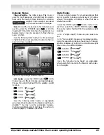
To view the Static-on-Screen™ value, press the
key, select the SPECIAL FUNCTIONS option
, and
set the STATIC UNBALANCE DISPLAYED option
to ON. The Static-on-Screen™ reading, see page 9, will
appear in the upper left-hand side of the screen.
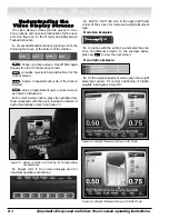
Optimization (Match Balance)
The Tire/Rim Weight Optimization procedure is used
to determine the best mating of tire and rim that will
result in the least amount of total unbalance of the
assembly. It requires two spins and two rotations of
the tire on the rim. Optimization may be needed when:
• The customer complains of ride problems.
• The balancer calls for total static weights in excess
of 3 ounces (85 grams) on passenger car tires.
Note:
A high unbalance may indicate the improper
mounting of the assembly on the balancer, or a rim that
is out of round or misformed, or a tire with a bubble or
other problem. If the unbalance is excessive, it may be
prudent to replace the rim, the tire, or both. If either is
replaced, do not continue with optimization. Balance
the new tire and rim and evaluate the readings.
If you choose to use Optimization to correct for a con-
dition, such as a large static unbalance, then select the
key for the menu screen, and then select the
OPTIMIZATION (MATCH BALANCE) option
.
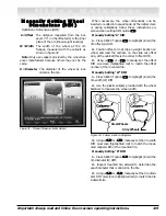
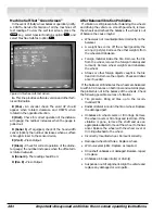
Follow the on-screen instructions for the TIRE/RIM
WEIGHT OPTIMIZATION procedure as outlined in
the following steps
.
Figure 30 - Tire/Rim Weight Optimization Screen
Note:
Use this procedure only after the wheel has
spun and weights are displayed.
1.
Rotate arrow on faceplate to 12 o’clock. Place a
mark (backside of the wheel) on the rim at 12 o’clock.
Press the NEXT option
.
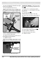
2.
Remove the wheel assembly from the balancer.
3.
Using a tire changer, rotate the tire 180 degrees
on the rim.
4.
Replace wheel assembly on balancer and align the
faceplate arrow with the mark on rim. Lower the hood
and press the NEXT option
. The wheel spins.
5.
Rotate the wheel until a red box appears at the
yellow arrows. Put a second mark (frontside of wheel)
on the rim at 12 o’clock.
6.
Rotate the wheel until a red box appears at the
green arrows. Put a third mark (frontside of wheel) on
the tire at 12 o’clock. Press the NEXT option
.
Note:
The rim unbalance and tire unbalance values
are displayed on the screen.
7.
Remove wheel assembly from balancer.
8.
Using a tire changer, align the mark on the rim
with mark on the tire.
9.
Replace the wheel assembly on the balancer.
Align the faceplate arrow with the previous mark (back-
side) on the rim to check improvement or just continue
with step 10.
10.
Press NEXT option
and balance the assembly
1
1
1
1
1
MENU
4
7
MENU
WARNING


