Coats Rim Clamp APX80A Operating Instructions Manual Download Page 10

6 •

Important: Always read and follow the operating instructions.

9.

Take time to experiment with the Duckhead

®

lock-

ing system (figure 8).

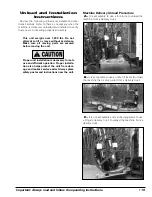
Figure 8 - Turn Slide Lock to Color As Shown, 

A

Green -

Duckhead Retracks Up, 

B

Yellow - Duckhead Descends

Slowly, and 

C

Red - Duckhead Locks into Position

Make sure the Duckhead is in the retracted
position before moving the tower forward,
to prevent wheel damage.

10.

Using the foot pedal, position the tower forward

(figure 9). See figure 8 for Duckhead movement and
locking. With the tower forward, allow tool to descend
on the tire sidewall (figure 9). Then move the tool
toward the rim and actuate the locking button. As the
tool locks into place, the Duckhead will move up and
back about 1/8-inch.

Figure 9 - Position Duckhead

11.

Check Duckhead

®

positioning. A plastic

Duckhead should not be very close to the rim edge
after it is locked. This clearance will be maintained as
long as the slide locking valve remains locked. The
operator may move the tower back out of the way and
back into place again without needing to reposition the
Duckhead (when clamping a like set of wheels).

H.

The tool clearance may change with

machine use and should be inspected often.
Failure to maintain the proper clearance may
result in damage to the wheel rim and/or tire.

K.

Normal tabletop rotation for demounting is

clockwise. Depress the tabletop pedal to
rotate this direction. To rotate the tabletop
counterclockwise, lift the pedal up with your
toe.

L.

Tabletop rotation can be stopped at any

time by removing your foot from the rotation
pedal.

At times during the mounting and
demounting procedure, the bead lifting tool
may encounter resistance and can be
thrown. Keep one hand firmly on the tool to
avoid possible tool disconnect. Use the
reversing feature to back out of jam-ups. A
thrown tool can cause injury.

12.

Apply tire manufacturer's approved rubber lubri-

cant liberally to entire circumference of both beads
after loosening and placing on tabletop. Using the top
bead loosening roller to hold down top bead while
rotating wheel will make lubrication easier (figure 10).

Figure 10 - Apply Rubber Lubricant to the Beads

13.

Insert smooth curved end of the bead lifting tool

over the clockwise end of Duckhead and below the
upper bead of the tire. Lift the bead up and over the
knob on the Duckhead (figure 11). Also, note the valve
stem position to the Duckhead, this position reduces
stresses in the bead and allows an easier bead lift.
Use Robo Arm to push down on the tire opposite the
Duckhead to allow bead to utilize the drop center area
of the rim.

A

B

C

Summary of Contents for Rim Clamp APX80A

Page 1: ...BADA Automotive Service Equipment and Tools Manual Part No 85000226 11 Revision 06 17 Installation Instructions Operating Instructions Safety Instructions Maintenance Instructions READ these instruct...

Page 2: ...Ratio of height to width aspect ratio Nominal width of tire in millimeters Passenger car tire U S DOT tire identification number Severe snow conditions Tire ply composition and materials used Max loa...

Page 3: ...ot take the place of safe operating practices Always wear durable work clothing during tire service activity Loose fitting clothing should be avoided Tight fitting leather gloves are recommended to pr...

Page 4: ...ire technicians safe By fol lowing the basic principles of R I M technicians can avoid situations that can cause catastrophic accidents like tire explosions R I M stands for read inspect and mount Rea...

Page 5: ...ting 8 9 Inflation 10 13 Bead Sealing 11 Bead Seating 12 Inflation 13 Stages of Inflation on a Conventional Tire and Rim 14 Mismatched Tires and Wheels 15 Maintenance Instructions 16 18 Separator Lubr...

Page 6: ...runflat and low profile tires B Bead Loosener Handle Pull handle up or down that controls operation of bead loosener shoe C Bead Loosener Shoe Pivoting shoe for loosening tire beads D Tire Bumper Guar...

Page 7: ...res through air hose and clip on chuck R Bead Sealing Nozzles Expands tire sidewall to bead seat area of rim to seal tire to rim and allow inflation S Lube Bucket Dispenser for rubber lubricant T Bead...

Page 8: ...ially or fully inflated tire is unsafe and causes excess movement and friction against the bumper pads and excessive wear on pivots Deflate the tire completely to prolong the life of your machine 1 De...

Page 9: ...l to move the clamps outward lift pedal up Engage the detent posi tion pedal in full up or full down position to maintain clamped or unclamped pedal position Avoid back injury use the tire lift or ask...

Page 10: ...ilure to maintain the proper clearance may result in damage to the wheel rim and or tire K Normal tabletop rotation for demounting is clockwise Depress the tabletop pedal to rotate this direction To r...

Page 11: ...pper Bead 15 For lower bead removal use Robo Arm to lift the tire up figure 13 and position the lower horizontal power roller figure 14 under the tire Figure 13 Lift the Tire for Lower Bead Removal Fi...

Page 12: ...match Do not let untrained persons operate tire changer and keep bystanders out of service area Forcing the tire onto the rim can cause bead damage If you damage the tire bead during mounting STOP rem...

Page 13: ...the knob on Duckhead figure 21A Figure 21A Use Power Roller To Hold Tire In Rim Drop Center 8 Use RoboArm to push down on tire opposite Duckhead to allow bead to utilize drop center area of rim Fig 2...

Page 14: ...ote The clip on chuck on the end of the hose should always be an open freeflow style with all parts in proper working order Position 1 Tire Pressure With the inflation hose attached to the tire valve...

Page 15: ...l for safe and proper oper ation Do not tamper with or attempt to adjust the pressure limiter Tires requiring inflation beyond 60 PSI should be inflated in a safety cage Bead Sealing 1 Position valve...

Page 16: ...operator or bystander Check tire pressure frequently If operator is unable to obtain Bead Seat something is wrong Deflate tire completely inspect tire and wheel correct any problems found relubricate...

Page 17: ...60 PSI On smaller volume tires the pressure may be higher 4 Release air pressure from tire by pressing the manual release valve button inflation hose must be attached to the valve stem Figure 25 Never...

Page 18: ...Most European import cars and many aftermarket alloy wheels are very tight and can be difficult to bead seat Also note that asymmet rical hump and run flat tires are extremely difficult to bead seat F...

Page 19: ...ed tire and wheel combinations can explode causing personal injury or death to operator and or bystanders Half Size Tires 14 5 15 5 16 5 17 5 etc Even Size Wheels 14 0 15 0 16 0 17 0 etc 15 5 Note the...

Page 20: ...sing other clamps then remove metal chips and dirt from the serrations with a wire brush every month F Check the tire pressure gauge function daily and check the accuracy monthly Use a pressurized tir...

Page 21: ...O 32 oil to full line air tool oil is an acceptable substitute Replace cap and clean up any spilled oil Important An air lock will form if the hose between the reservoir and injector is ever empty of...

Page 22: ...s shown and described below at least monthly 1 Remove tires and or wheels from the machine 2 Connect the inflation hose to an empty service tank with a pressure gauge gauge should read 0 Use a certifi...

Page 23: ...s necessary for safe use and efficient operation Proper installa tion also helps protect the unit from dam age and makes service easier Always place safety poster and instructions near the unit Machin...

Page 24: ...machine install axle and wheels as shown 3 Remove ramp planks and position as shown 4 Move jack to front add air pressure to machine 5 Slowly push machine off pallet 6 Locate machine in shop at prope...

Page 25: ...axle and wheels as shown 5 Slowly push machine forward to position offload bracket over jack 6 Jack up front of machine and slowly move machine off pallet 7 Locate machine in shop at proper location a...

Page 26: ...on the right side of the rear of the machine A 1 4 ID hose or pipe for connection to the machine is satisfactory Sufficient air pressure assures good performance Electrical Source Electrical models r...

Page 27: ...Important Always read and follow the operating instructions 23...

Page 28: ...e on a rim inspect the rim for rust tough spots bent edges or cracks that could prevent the tire from seating right If you spot any of these problems don t mount the tire until the rim has been checke...

Reviews: