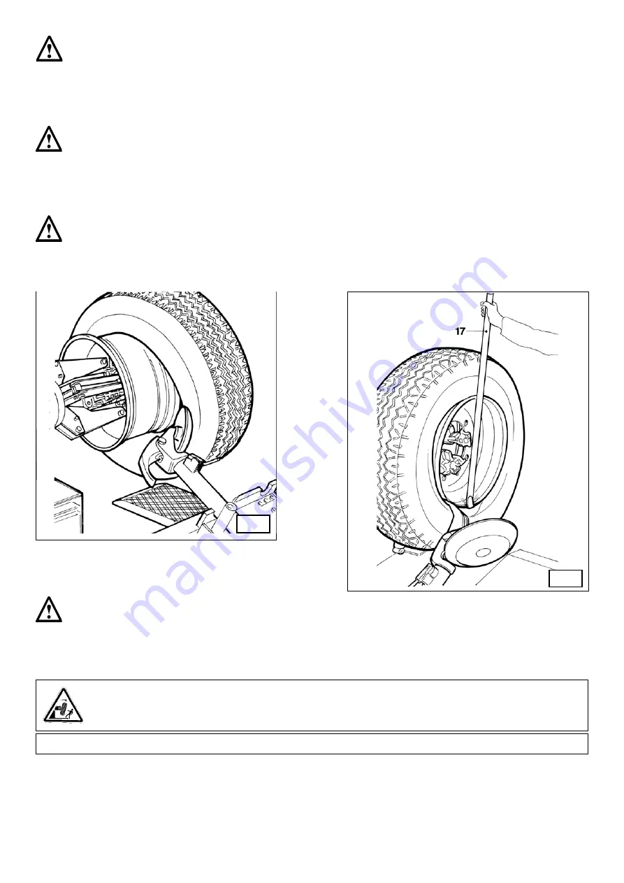
background image

1

- Insert lever 


 (17, Fig. I) between rim and bead at the right of the tool.

-Press down on the lever and lower the wheel to bring the edge of the rim about 2 inch (5 cm) from the hooked tool.

-Turn the wheel anticlockwise pressing down on lever 


 until the bead is completely off.

-Move the tool carrier arm to its non-working position and then move it to the inside plane of the wheel.

- Rotate the wheel and at the same time move the hook tool forward inserting it between rim and bead until it is anchored to the bead 

(See Fig. I).

-Move the rim 1,5 - 2 inch (4-5 cm) from the tool taking care that it does not unhook from the bead.

-Move the hook tool towards the outside until the red reference dot is by the outside edge of the rim.

-Place the tool carriere arm in its working position, then use the bead disc to push against the  inside face of the tire  (see fig. H) it is best 

to do this with the wheel turning.

-Move the rim about 4-5 cm from the tool making sure the hook does not detach from the rim.

Take the mobile control unit to work position C.

Take the mobile control unit to position B.

Take the mobile control unit to work position D.

  H

  I

-Always keep the rotating counterclockwise, while pushing with  the bead disk

Turn the wheel counterclockwise pushing with disk until the tire comes completely off the rim.

DANGER!

When the beads come off the rim, the tire will fall. Check to make sure there are no by-standers in the work 

area.

MOUNTING 

Tubeless tires can be mounted using either the 

bead breaker disk 

or the 

hook tool

If the tire is not problematic, use the bead loosener disk. 

If the tire is very rigid, the hook tool must be used.

Take the mobile control unit to work position B.

Summary of Contents for CHD-9043

Page 1: ...ructions before placing unit in service KEEP these and other materials delivered with the unit in a binder near the machine for ease of reference by supervisors and operators 8501079 00 Revision 07 08...

Page 2: ...LS 8 10 IDENTIFICATION OF CONTROL 9 11 WORKING POSITION 9 12 CORRECT OPERATION CHECKS 9 13 OPERATION 11 13 1 Rim clamping 11 Light alloy rim clamping 13 2 Tubeless and supersingle tires 12 Bead loseni...

Page 3: ...authorized personnel Any unauthorized changes or modifications to the machine in particular to its electric system relieve the manifacturer from all liability Removing or tampering with the safety dev...

Page 4: ...Keep the packing for possible future transport UNPACKING 7 INSTALLATION Choose the place the machine is to be installed in compliance with current work place safety regulations The floor should not be...

Page 5: ...side drawing as well as the table herebelow If a floor of this type is not available on site fastening points of the specified concrete quality are acceptable The surface on which the universal tire c...

Page 6: ...ighted on the data plate fixed to the tire changer Check to make sure the shop electric wiring circuit is dimensioned sufficiently to carry this Work on the electric system even if minor must be done...

Page 7: ...s of the machine Necklaces bracelets and too large clothes can be dangerous for the operator B 6 B 7 12 5 6 1 Lifting bracket 2 Self centering chuck holding arm 3 Self centering chuck 4 Sliding ramp 8...

Page 8: ...o not use the tire changer if one or more labels are missing Do not add any object that could prevent the operator from seeing the labels Use ref code 2019113 to order labels set if needed 3005419 300...

Page 9: ...the tool and in position f locks the tool bringing it back to working position in position g moves the tool carriage leftwards and in position h moves it to the opposite side The chuck switch 9 fig C...

Page 10: ...hooked in working position Push the lever rightwards h to have the tool carriage moved rightwards push it leftwards to have the tool carriage moved to the opposite side 4 Depress the right pedal 10 F...

Page 11: ...dequate lifting device must be used 4 Continuing to operate from the mobile control unit lift or lower the arm in order centre the self centering chuck 3 fig A relative to the rim 5 With the jaws 22 f...

Page 12: ...bayonet like mounting into the clamp support of the self centering chuck see fig E 7 Thanks to a wing screw the clamp can be locked on the support Lock the rim as illustrated in fig E 8 The specially...

Page 13: ...ng the claw 18 fig G can be lowered so that it is out of the way 9 Take the mobile control unit to work position D 4 Operating from the mobile control centre manoeuvre the wheel until the outside of t...

Page 14: ...rriere arm in its working position then use the bead disc to push against the inside face of the tire see fig H it is best to do this with the wheel turning Move the rim about 4 5 cm from the tool mak...

Page 15: ...5 1 inch 1 2 cm inside the edge of the rim Begin to turn the spindle clockwise checking to make sure that with a 90 turn the second bead begins to slip into the centre well 11 When the bead is fully m...

Page 16: ...nit to work position D 7 Remove the tool from the tire 8 Move the tool carrier arm to its non working position Move it to the outside face of the tire and rehook it in this position 9 Turn the tool 18...

Page 17: ...ored to the tool 3 Move the rim 1 5 2 inches 4 5 cm from the tool taking care that it does not unhook from the bead 4 Move the hook tool towards the outside until the red reference dot is by the outsi...

Page 18: ...ING 1 If the rim has been removed from the spindle put it back on the spindle as described in the section on rim clamping 2 Lubricate both beads and the rim with tire manufacturer recommended lubrican...

Page 19: ...d then remove the locking ring NB The purpose of this operation is to allow the valve to be loose so that it is not ripped out during second bead mounting 19 Lift the tire again and attach the g clamp...

Page 20: ...ully and be prepared to stop the disk immediately once the bead has been broken so as not to damage the valve and the inner tube 6 Repeat this procedure but this time bring the disk against the split...

Page 21: ...ed this ring can be removed with the special lever 20 Fig Z or with the help of the bead disk 6 Remove the O ring 7 Move the tool carrier arm 14 Fig D back from the edge of the rim Release the hook an...

Page 22: ...icate both beads and the rim with tire manufacturer recommended lubricant Take the mobile control unit to work position D Take the mobile control unit to work position B 3 Move the ramp to be able to...

Page 23: ...forward with the spindle turning until you observe the O ring seating 8 Lubricate the O ring and its seating 9 Position the locking ring on the rim with the help of the disk as shown in Fig Y Move the...

Page 24: ...DTE 25 Castrol Hyspin AWS 46 Chevron RPM EP Hydraulic Oil 46 BP Energol HLP 4 Frequently check the oil level in the gear unit which when the tool carrier bracket is completely lowered down should not...

Page 25: ...inches 60 mm wide and of a lenght sufficient to bring the hook of the belt above the tyre changer 5 With the special belt ring bring the 2 ends of the belt together and lift with a sufficiently stron...

Page 26: ...WARNING If this machine catches fire use dust or CO estinguishers only 2 These units are considered as special waste material and should be broken down into uniform parts and disposed of in complianc...

Page 27: ...27...

Page 28: ...HENNESSY Industries INC 1601 J P Hennessy Drive LaVergne TN 37086 3565 USA Toll Free 800 688 6496 www ammcoats com...

Reviews: