5
B/5
A
98.4 inches (2,500 mm)
1
4
7.2
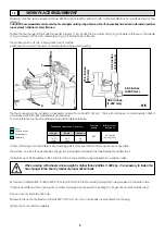
The tire-changer must be installed on a levelled concrete floor at least 8” (20 cm) . thick, with a minimum concrete quality of B25 in
accordance with DIN 1,045 requirements (foundations).
For your reference see the side drawing as well as the table herebelow.
If a floor of this type is not available on site, fastening points of the specified concrete quality are acceptable.
The surface, on which the universal tire-changer is to be installed, must be flat and well levelled in all directions.
Inclinations up to 0,25% relative to the horizontal can be compensated using suitable shims, wedges or alike.
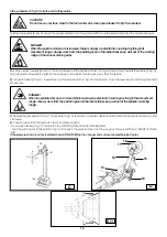
By means of a Widia bit Ø 16 drill a 0.630 inch hole (130 mm) into the floor passing through the holes provided on the base frame.
If there is an additional floor covering (B), or if shims or wedges are necessary for levelling (C), longer anchor bolts must be used.
Place an anchor bolt into each hole.
Make sure the anchor bolts extend at least 4.90” (125 mm). into the concrete slab, as indicated in the drawing.
Tighten the anchor bolts completely.
Ground
Reinforced concrete
Electrowelded grid
Pebble gravel
When working with wheels, whose weight is higher than 2,204 lbs (1,000 kg)., it is necessary to fasten the
tire-changer to the floor by means of proper anchor bolts.
Maximum machine space requirements are 88.2X6.3 inches (2,240x 1,640 mm) with a minimum distance from walls as shown in the
diagram.
CAUTION! These measurements are also the tire changers working range. Persons other than specially trained and authorized operators
are expressly forbidden to enter this area.
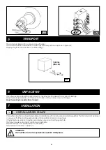
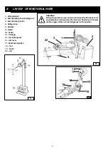
Position the tire changer lifting it with the specific bracket (1, Fig. A) with the tool carrier arm (2, Fig. A) lowered all the way, the spindle
(3, Fig. A) closed and the tool carrier slide (4, Fig. A) at its stop close to the arm.
The mobile control unit has no fixed position, but it must be
positioned in a way that the user can observe the machine when working
WORK PLACE REQUIREMENT
98.4 inches
(2,500 mm)
27.5 inches (700 mm)
39.3 inches
(1,000 mm)
Foundationsdimensions inch (cm).
Concrete
quality
Min. pressure
resistence
Length
Width
Thickness
B25
937 lbs/sqft
(425 Kg / cm
2
)
78,74
(200)
64,5
(164)
5,9
(15)


