User’s Manual
Page i
USER'S MANUAL
TABLE OF CONTENTS
Contents Page #
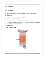
1.0
OVERVIEW ..................................................................................................................... 1
2.0
FEATURES ..................................................................................................................... 1
3.0
DESCRIPTION ................................................................................................................ 1
4.0
TERMINAL BOARD ........................................................................................................ 2
4.1
POWER ................................................................................................................................... 2
4.2
INPUT SIGNAL........................................................................................................................ 2
4.3
INTERNAL CIRCUIT ............................................................................................................... 3
4.4
INPUT SIGNAL TOUCH .......................................................................................................... 3
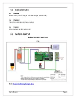
5.0
INDICATOR LED ............................................................................................................ 4
5.1
POWER ................................................................................................................................... 4
5.2
ENABLE .................................................................................................................................. 4
5.3
TOUCH .................................................................................................................................... 4
6.0
WARNIG SAMPLE .......................................................................................................... 4
Page 1: ...USER S MANUAL VER 1 5 PTS 1 PLASMA TOUCH SENSOR Rev 1 AUGUST 2020...
Page 2: ...NTENTS Contents Page 1 0 OVERVIEW 1 2 0 FEATURES 1 3 0 DESCRIPTION 1 4 0 TERMINAL BOARD 2 4 1 POWER 2 4 2 INPUT SIGNAL 2 4 3 INTERNAL CIRCUIT 3 4 4 INPUT SIGNAL TOUCH 3 5 0 INDICATOR LED 4 5 1 POWER 4...
Page 3: ...with signals between 5 to 24VDC or Open collector Status LEDs Electromechanical Relays with NO and NC positions Can be powered with 12 or 24VDC Signals and power connections fully isolated from the p...
Page 4: ...to these terminals can cause damage to the board and or the power source 4 0 TERMINAL BOARD 4 1 POWER Regulated 12VDC to 24VDC at 80mA is required to power this board 4 2 INPUT SIGNAL While this board...
Page 5: ...obing circuit is being powered by capacitors and the signals handled by relays 4 4 INPUT SIGNAL TOUCH The enable signal needs to be active while sensing is enabled This to have the circuit and relays...
Page 6: ...1 POWER Switch on the power supply of red LED will light Power LED 5 2 ENABLE The LED on indicates that the is enabled 5 3 TOUCH When touched red LED will turn on 6 0 WARNIG SAMPLE WIRING SAMPLE WITH...
Page 7: ...ines Neither DUNCAN USA LLC nor Arturo Duncan are liable for any accidents resulting from the improper use of these devices This product is not a fail safe device and it should not be used in life sup...