background image

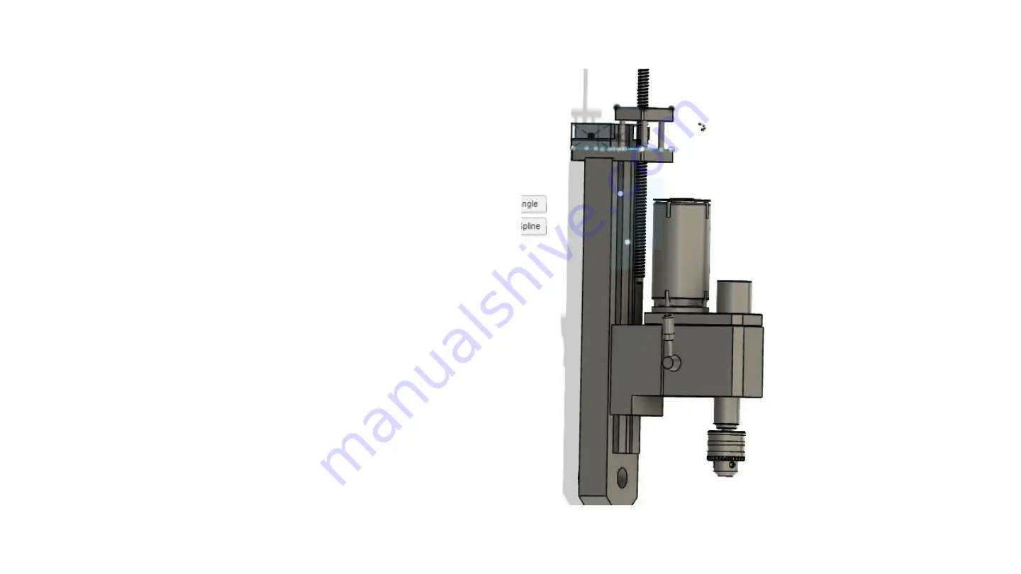
Slide the Z axis assembly down on top of the column. 
With the column top plate setting on the top of the 
column, move it around until the 3/8-16 threaded 
hold is in the slot on the top of the column top plate. 
Thread the 3/8-16 bolt that is provided into the 
column clamp bar with the washer provide. Screw the 
bolt in until it is loosely on top of the column top 
plate. Do not tighten at this point.

Summary of Contents for Seig X2

Page 1: ...Assembly Instructions for Seig X2 and X2D Benchtop Mini MIll...

Page 2: ...The kit includes 3 16mm ball screw and ball nut assemblies 3 NEMA 23 stepper motor mounts All necessary mounting hardware All new thrust bearings assemblies All new shaft connectors to connect the bal...

Page 3: ...ll do but lithium is recommended An electric drill To prepare the machine if new please remove all the rust prohibitive applied by the factory If used please remove all shavings and dirt from the mach...

Page 4: ...u must be very careful when removing the ball nut from the ball screw using the carboard tube supplied You will have to unscrew the nut from the ball screw onto the cardboard tube to assure that you d...

Page 5: ...the left side table endplate from the table Now loosen the jam nuts that hold the gib in place Once these are loosed use an Allen wrench to back out the gib adjustment screws The table is now loose a...

Page 6: ...ad screw nut in the Y axis cross slide Be sure and mark these two bolts as you will need them later for re assembly You should be able to lift the lead screw and nut up from the base Set it to the sid...

Page 7: ...e two bolts that hold the bearing housing from the front of the base Then remove the bolt that holds the Y axis lead screw nut from the cross slide casting You should now be able to unscrew the lead s...

Page 8: ...djustment screws and back out the gib adjustment screws as before The are located on the right side of the Y axis cross slide casting You should now be able to slide the Y axis cross slide casting fro...

Page 9: ...ll machinist jacks You will be moving the head up and down using the handles on the fight side of the head However when you remove the rack gear the head is free to fall down and must be secured in pl...

Page 10: ...ly raise the spindle motor and mount from the head Be extra careful not to drop it or you may pull the wires from the electronics box or the motor itself You will need something to set the motor on wh...

Page 11: ...e you will need to secure the head in place The next step will remove the ability to raise or lower the head using the Z axis cranking levers Wooden blocks or jacks between the spindle and the table O...

Page 12: ...ped in place the remaining screws removed from the rack gear rotate the head raising lowering levers to raise the rack gear from the top of the column and remove it It is no longer needed Pull rack up...

Page 13: ...he small Phillips screws Remove the set screw that holds the crank levers in place and pull it off it is no longer needed Then remove the thin metal cover The remove the housing that holds the pinion...

Page 14: ...ay no longer raise or lower the head with the cranking levers Start by removing the set screw that locks the handle assembly to the pinion gear that goes through the head Set it to the side it is no l...

Page 15: ...hile attaching the screws that connect it to the column Align the holes in the clamp bar and use the screws provided attach it to the column by putting the screws into the holes on the column that the...

Page 16: ...xis cross slide to the base first Note If your machine has a lifting device mounted to the left side of the headstock it must be removed There is no instruction for this as there are only two screws n...

Page 17: ...ess to the bottom of the base and raised so that you can insert the Y axis ball screw assembly through the bottom of the base into the hole at the front of the casting You will then need to set the ba...

Page 18: ......

Page 19: ...ere Do not tighten at this point screw in just enough to engage the gib Note the gib has indentions that the end of these screws go into Make sure they are just inside the indentions so that when you...

Page 20: ...is is shown with a left sided mount If you decide to mount it on the right side you will need to remove the ball nut from the screw and reverse To do so you must be very careful when removing the nut...

Page 21: ...e re insert them through the ball nut mount and into the Y axis cross slide base Note the orientation of the nut the recirculation tubes are on the bottom side of the nut This must be oriented this wa...

Page 22: ...nt is on the correct side facing out It can be identified by have a measuring scale on it Note it can be installed from either side Go slowly as the ball nut mount and table bottom are very close In f...

Page 23: ...Some grinding may be required...

Page 24: ...n the table end plate is off set to match the dovetails but the holes that mount it to the table are in the center of the table Therefore the end plates can be installed incorrectly Please make sure t...

Page 25: ...ok nut and stepper motor mount on the threaded end of the ball screw Do not tighten the bolts at this point Install the ball nut receiver making sure the roller support bearing is in the receiver Do n...

Page 26: ...e much easier since it is shipped assembled and all you have to do is remove the lift rod and slip the assembly down on to the top of the column You may have to rotate the ball nut to raise or lower t...

Page 27: ...The column clamp bar is already inside the column...

Page 28: ...of the column move it around until the 3 8 16 threaded hold is in the slot on the top of the column top plate Thread the 3 8 16 bolt that is provided into the column clamp bar with the washer provide...

Page 29: ...the ball nut and lower the ball screw down until the holes in the end of the side plates align with the holes in the side of the head that were left when you removed the rack and pinion from the head...

Page 30: ...t fit into at dis assembly Now move the side plates Down until the holes align insert the shoulder bolt provided through the side plate and into the lift pin You can now move to the other side and ins...

Page 31: ...o install the shaft couplings on the end of the X and Y ball screw shafts Put a shaft into the other end of the coupling and use a drill to move the X and Y axis Select an axis to adjust and place the...

Page 32: ...move the axis all the way to one end and just snug the bolts on the table end plate Then move it in the other direction until it is at the other end of the table Snug the bolts on that table end plat...

Page 33: ...gibs This is extremely important If the gibs are too tight the machine will not move properly And if the stepper motors are installed at this point they may bind and stall On the X and Y ball nut moun...

Page 34: ...t 3 Now move the Y axis away from the operator and towards the column Tighten the Y axis ball nut mount bolt located at the front of the Y axis cross slide casting in the center near the bottom 4 Agai...

Page 35: ...alled 2 The steps are the same move the axis to the top of the column and snug the 3 8 26 bolt that is holding the column top plate to the column Before tightening Align the column top plate to the co...

Reviews: