2
Description
The Flow rate sensor 0387i measures the velocity of flowing water. It can be used to
study the discharge, flow patterns, and sediment transport of flowing water.
The Flow rate sensor is equipped with impeller rod with 5-meter cable. To assemble
the sensor, simply unfold the four sections of the impeller rod and slide them
together. Connect the rods to one another with a small push.
The sensor is delivered with three riser rods (short, medium, and long). The total
length of the impeller rod, including all 3 risers, is 1.5 m.
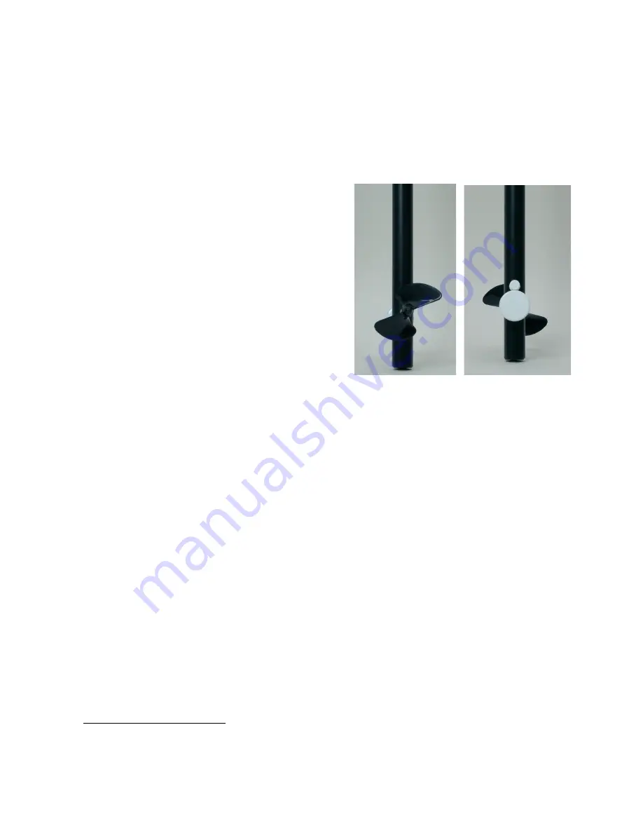
When the Flow rate sensor is placed in a
stream, water flows against the blades of the
impeller, causing it to turn. The faster the
water flows, the faster the impeller turns. A
bar magnet rotating with the impeller triggers a
reed switch with each half rotation. The switch
sends a pulse to the signal conditioning box,
where the pulses are converted into a voltage
signal that is proportional to flow rate.
The Flow rate sensor is equipped with a BT-
plug and can be connected to the following
CMA interfaces:
€
Lab
,
CoachLab II/II
+
and
U
LAB. Furthermore the sensor can be used
with Texas Instruments CBL
™
, CBL2
™
and
Vernier LabPro.
Sensor specifications
The Flow rate sensor has a memory chip (EEPROM) with information about the
sensor. Through a simple protocol (I
2
C) the sensor transfers its data: name, quantity,
unit and calibration to the interface
1
.
Storage and Maintenance of the Flow rate sensor
When you have finished using the Flow rate sensor, simply rinse it with clean water
and dry it using a paper towel or cloth. The probe can then be folded up and stored.
To prolong the life of your Flow rate sensor, we recommend that the moving parts of
the impeller rod be lubricated, after every few field uses.
When using the impeller rod, avoid hitting the impeller blade on rocks and other
hard surfaces. If the impeller blade is bent, it will decrease the accuracy of the
sensor.
1
This is valid for the following interfaces: CMA
€
Lab
,
BT inputs of CoachLab II/II
+
and
U
LAB,
TI CBL
™
and CBL2
™
, and Vernier LabPro.
Figure 2
.
Left: the sensor impeller
Right: the sensor bar magnet with reed
switch.


