Automation Motor Mix Operations Manual v 2.0 2/00 Page 8
Standard Operations
Description of Controls and Displays
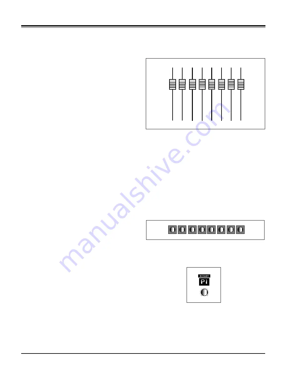
Fader Input
When the faders are not being moved by the computer, you can move
them. Motor Mix disengages the motor so you can make level changes.
The motor will stay disengaged as long as you continue to move the fader.
If you wish to keep the fader stationary but keep the motor disengaged,
press and hold the "SHIFT" switch. The motors will engage as soon as the
"SHIFT” switch is released. If you wish to make very small fader move-
ments quite slowly, press the “SHIFT” switch. This keeps the faders touch
released during the small fader movements.
Shift “double click”
Click the shift switch twice quickly and its LED will blink. It is like holding
the “SHIFT” switch down to hold faders punched in. Any fader that is
punched in will remain punched in until either the “SHIFT” switch or the
“write” shift is pressed. Press the “shift” switch twice quickly to exit. The
“SHIFT” switch still performs its normal functions while in this mode.
The yellow LED (funct B) below the “write” LED lites to show that one or
more faders are punched in. A punched in fader will send moves out and
the motor(s) will remain off. Press the “write” or “SHIFT” switch to punch
out all faders, and the LED will extinguish. If the transport is playing,
pressing “Stop”, “PLAY”, “FFWD” or “REW” will also punch out the faders.
If a fader is being moved by the computer, press a “burn” button to punch
the fader in and it will remain punched in regardless of the “SHIFT” switch.
The “funct B” LED lites to show that faders are also punched in. Press the
channel “burn” switch a second time to punch it out. Press the “write” or
“SHIFT” switch to punch out all faders, and the “funct B” LED will extin-
guish. If the transport is playing, pressing “Stop”, “PLAY”, “FFWD” or
“REW” will also punch out the faders.
Rotary Pots
The 8 rotary pots on Motor Mix send out relative information only, since
the application always knows the current setting. The bottom row of the
LCD indicates the current pot settings either graphically or numerically
depending on the application. The pots simply add or subtract to the
current setting. These pots are intended to control pan, aux send levels,
equalizers, and any plug-ins you may have installed.
Rotary Selector
Used in conjunction with the 7 segment display to select what the rotary
pots are controlling. Normally, the pots start out controlling pan. Rotating
this selector should cause the pots to change their task. Typically, they
would go from pan to aux1 to aux2 to aux3, etc. The 7 segment display
should give some indication of what the rotary pots are controlling:
P=(pan), A1=(aux1), A2=(aux2), etc. The utility of these controls depends
on how the host application has implemented them.


