


ACCELERATOR AND BRAKE PEDAL GROUP
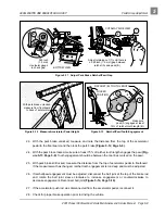
Pedal Group Adjustment
2001 Pioneer 900 Gasoline Vehicle Maintenance and Service Manual Page 5-11
5
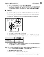
4.1. Remove the electrical box screw and cover. See preceding DANGER.
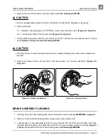
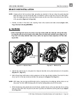
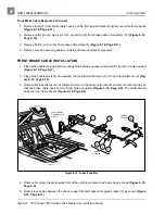
4.2. Loosen the jam nuts (18) and disconnect the accelerator rod (17) at the accelerator pedal. Adjust
the length of the rod (Figure 5-18, Page 5-12) so the indicated cam edge is parallel with the edge
of the electrical component box as shown (Figure 5-17, Page 5-11). See following CAUTION.
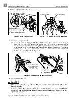
∆ CAUTION
• After accelerator rod adjustment, make sure that approximately the same number of threads are
exposed at each end of the accelerator rod.
• When loosening jam nuts on the accelerator rod with one end disconnected, hold the disconnected
accelerator rod with locking pliers.
• When tightening jam nuts on the accelerator rod, hold the disconnected ball joint with locking pliers.
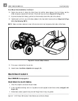
4.3. Reconnect the accelerator rod at the accelerator pedal.
4.4. Before tightening jam nuts on accelerator rod, set park brake to first ratchet and pawl position.
Depress accelerator pedal and make sure the following events occur in the
exact order shown:
4.5. If the events above occur as they should, hold the ball joint at each end of the accelerator rod with
pliers and tighten the accelerator rod jam nut against it.
4.6. Ensure that the events occur as described in step 4.4 above.
NOTE: After the accelerator pedal and rod are adjusted, the final governed engine RPM should be set to
3100 (±30) RPM. See Engine RPM Adjustment, Section 14, Page 14-13.
4.7. Install the electrical box cover and screw.
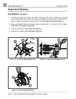
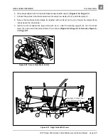
5. Adjust the brakes. See Brake Adjustment, Section 6, Page 6-16.
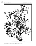
Figure 5-17 Accelerator Cable
EVENT
APPROXIMATE
PEDAL TRAVEL
Park brake release
0° to 4°
Carburetor throttle actuation
8° to 12°
RETAINING
NUTS
TOP VIEW OF THE
ELECTRICAL
COMPONENT
BOX
CAM
PARALLEL
WITH
BOX