FE350 ENGINE
Crankshaft and Counterbalance
2001 Pioneer 900 Gasoline Vehicle Maintenance and Service Manual Page 13-35
13
Oil Pump Installation
∆ CAUTION
• Do not allow any dust or other foreign matter into the oil pump.
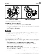
1. Installation is the reverse of removal.
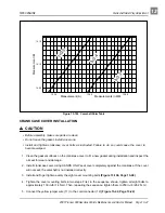
3. Install six bolts (1 - 6) and finger tighten. Then tighten to 7 ft-lb (9.5 N·m) in the sequence shown (Fig-
ure 13-65, Page 13-33). After tightening bolts, check the torque of the first bolt.
CRANKSHAFT AND COUNTERBALANCE
Read DANGER and WARNING on page 13-1.
Crankshaft and Counterbalance Removal
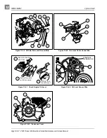
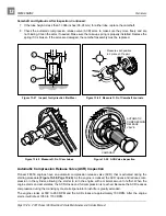
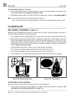
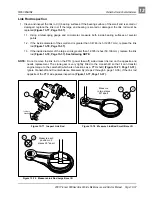
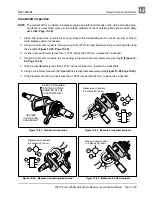
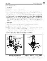
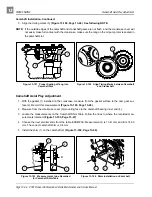
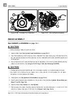
1. Remove the four nuts (1) and pull out the counterbalance guide shaft (2) and the O-ring (3) (Figure 13-
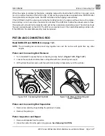
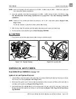
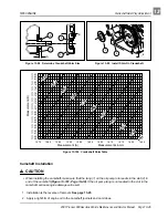
2. Pull out the crankshaft and the counterbalance together as an assembly (Figure 13-74, Page 13-35).
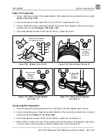
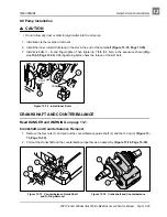
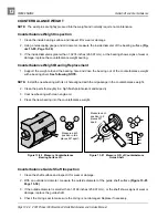
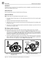
Figure 13-72 Install Inner Rotor
Figure 13-73 Counterbalance Guide Shaft
and O-Ring Removal
Figure 13-74 Crankshaft and Counterbalance
TANG
6
SLOT
5
2
1
3
2
3

