
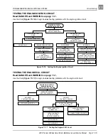
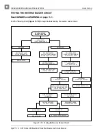
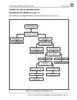


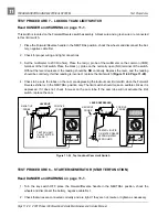

TROUBLESHOOTING AND ELECTRICAL SYSTEM
Test Procedures
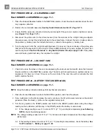
Page 11-24 2001 Pioneer 900 Gasoline Vehicle Maintenance and Service Manual
11
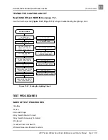
Test Procedure 3 – Ground Straps, Continued:
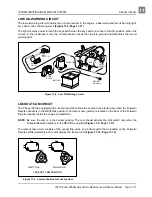
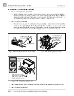
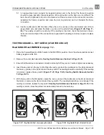
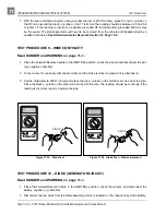
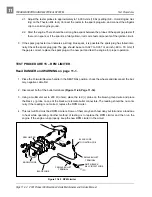
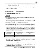
2. Check the starter/generator ground strap.
2.1. Set the multimeter to 200
Ω
(ohms). Place the red (+) probe on the (A2) terminal of the starter/
generator and place the black (–) probe on the vehicle frame (Figure 11-24, Page 11-24). The
reading should be continuity. If the reading is incorrect, clean and tighten wire connections. If the
connections are good and the reading is incorrect, repair or replace the wire.
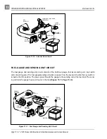
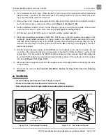
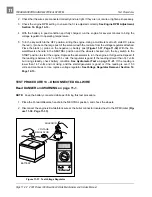
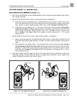
3. Check the engine ground strap.
3.1. Place the red (+) probe of the multimeter on the ground strap terminal end located on the oil filler
bracket on the engine (Figure 11-25, Page 11-24). Place the black (–) probe on the vehicle
frame. The reading should be continuity. If the reading is incorrect, clean and tighten wire connec-
tions. If the connections are good and the reading is incorrect, repair or replace the wire.
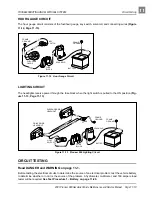
4. Check voltage regulator ground connection (at battery frame ground). Make sure it is clean and tight.
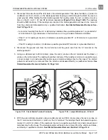
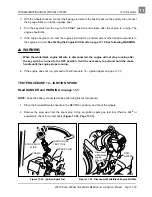
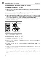
5. Check the battery ground cable.
Figure 11-24 Test Starter/Generator Ground Strap
Figure 11-25 Test Engine Ground Strap
Figure 11-26 Battery Ground Cable Test
F2
A2 TERMINAL
WIRE TO FRAME NEXT
TO BATTERY
Club Car
The engine ground
is attached to the
oil filler bracket,
and the
frame i-beam.
2m
20
m
200
m
2k
200
200
200
200
20
2
200
m
500
20k
200k
2000
k
Ω
Ω
1000
OFF
WAVETEK
5XL
V
V
V
A
!
!
COM
200nA
MAX
1000 ---
750V
FUSED
Place black (–)
probe on
frame.
Disconnect the 6 gauge
black wire from the battery.
Place red (+) probe on
disconnected end of wire.