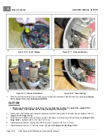
ELECTRIC VEHICLE - MOTOR
External Motor Testing
16
TEST PROCEDURE 3 – Armature Circuit Open
See General Warnings on page 1-1.
1.
Disconnect the batteries and discharge the controller.
See Disconnect the Batteries – Electric Vehicles,
2.
Disconnect wires from the A1 and A2 terminals on the motor using two wrenches to prevent posts from turning.
Set a multimeter to 200 ohms and place the red (+) probe on the A1 terminal and black (–) probe on the A2
terminal. The multimeter should indicate continuity. If the reading is incorrect, a possible open or poor contact in a
brush assembly and/or open armature windings may be the cause. The motor will need to be removed from the
vehicle and repaired by a qualified technician.
See Motor Removal on page 16-4.
3.
If reading is correct, reconnect the motor wires.
See Motor Installation on page 16-15.
4.
Connect the batteries.
See Connect the Batteries – Electric Vehicles, Section 1, Page 1-5.
TEST PROCEDURE 4 – Field Circuit Open
See General Warnings on page 1-1.
1.
Disconnect the batteries and discharge the controller.
See Disconnect the Batteries – Electric Vehicles,
2.
Disconnect wires from the F1 and F2 terminals on the motor using two wrenches to prevent posts from turning.
Set a multimeter to 200 ohms and place the red (+) probe on the F1 terminal and the black (–) probe on the
F2 terminal. The multimeter should indicate continuity. If the reading is incorrect, a possible open field coil or
bad connections at the terminals may be the cause. The motor will need to be removed from the vehicle and
repaired by a qualified technician.
See Motor Removal on page 16-4.
3.
If reading is correct, reconnect the motor wires.
See Motor Installation on page 16-15.
4.
Connect the batteries.
See Connect the Batteries – Electric Vehicles, Section 1, Page 1-5.
2021 Carryall 300 Maintenance and Service Manual
Page 16-3
Summary of Contents for Carryall 300 2021
Page 2: ......
Page 16: ......
Page 551: ...80 2018 by Kohler Co All rights reserved KohlerEngines com 17 690 15 Rev...
Page 565: ...GASOLINE ENGINE HARNESS Wiring Diagrams Gasoline Engine Harness 26...
Page 566: ...Page intentionally left blank...
Page 567: ...GASOLINE KEY START MAIN HARNESS Wiring Diagrams Gasoline Key Start Main Harness 26...
Page 568: ...Page intentionally left blank...
Page 569: ...GASOLINE PEDAL START MAIN HARNESS Wiring Diagrams Gasoline Pedal Start Main Harness 26...
Page 570: ...Page intentionally left blank...
Page 571: ...GASOLINE INSTRUMENT PANEL HARNESS Wiring Diagrams Gasoline Instrument Panel Harness 26...
Page 572: ...Page intentionally left blank...
Page 573: ...GASOLINE FNR HARNESS Wiring Diagrams Gasoline FNR Harness 26...
Page 574: ...Page intentionally left blank...
Page 575: ...ELECTRIC MAIN HARNESS Wiring Diagrams Electric Main Harness 26...
Page 576: ...Page intentionally left blank...
Page 577: ...ELECTRIC INSTRUMENT PANEL HARNESS Wiring Diagrams Electric Instrument Panel Harness 26...
Page 578: ...Page intentionally left blank...
Page 579: ...ELECTRIC ACCESSORIES HARNESS Wiring Diagrams Electric Accessories Harness 26...
Page 580: ...Page intentionally left blank...
Page 588: ...NOTES...
Page 589: ...NOTES...
Page 590: ...NOTES...
Page 591: ...NOTES...
Page 592: ...NOTES...
Page 593: ...NOTES...
Page 594: ...NOTES...
Page 595: ......
Page 596: ......

