


ELECTRIC VEHICLE - ELECTRICAL SYSTEM
TROUBLESHOOTING
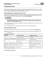
Test Procedures
12
2976
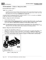
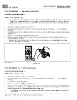
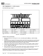
Figure 12-4
Testing the Fuse
1.
If necessary, see Testing Basics on page 12-12.
2.
Access the fuses but do not remove them. Fuses are found at the following locations:
–
On Controller Mounting Plate:
15-amp fuse to DC/DC converter, 2-amp fuse to connected car device
(Guardian/Visage V3 Circuit), and 15-amp fuse to electric powertrain
–
Under Floorboard Near MCOR:
20-amp fuse from DC/DC converter to accessories
–
Under Front Cowl:
15-amp fuse to cab, 10-amp fuse to brake lights, horn and turn signals, 7.5-amp fuse to
headlights and taillights, 10-amp fuse to 12-volt power strip and power point
–
On Main Harness Near Controller Mounting Plate:
30-amp fuse for charger receptacle harness
–
On Main Harness Forward of the 30-Amp Fuse:
1-amp fuse for charger interlock circuit
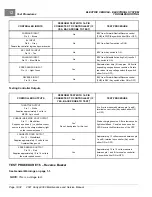
3.
2-Amp and 15-Amp ATC Fuses On Controller Mounting Plate and 30-Amp ATC Charger Receptacle Fuse:
With the batteries connected and the Run/Tow switch in the RUN position:
3.1.
Probe the two, small metal contacts on the top of the fuse
3.2.
Each contact should show BPV.
3.3.
If only one side shows BPV, replace fuse.
3.4.
If neither side of fuse shows BPV, do the following:
– Check BPV.
– Check condition and connection of large red wires at solenoid.
– Check sonic weld_8 in main wire harness.
– For one of the 15-amp ATC fuses, check Run/Tow switch to make sure it is in RUN position.
– Check if 12 gauge red wire is coming off large post on solenoid.
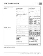
4.
1-amp AGC Glass Fuse Only:
With the Run/Tow switch in the RUN position:
4.1.
Probe the wire on each side of the fuse with insulation-piercing probes.
4.2.
Each probe should show 42 to 46 volts.
4.3.
If only one side shows voltage, replace fuse.
4.4.
If neither side of fuse shows voltage, do the following:
– Check Run/Tow switch to make sure it is in RUN position.
– Check diode_1 in main wire harness.
– Check 10k ohm in main wire harness.
– Check 15-amp ATC fuse on controller mounting plate.
2021 Carryall 300 Maintenance and Service Manual
Page 12-17
Summary of Contents for Carryall 300 2021
Page 2: ......
Page 16: ......
Page 551: ...80 2018 by Kohler Co All rights reserved KohlerEngines com 17 690 15 Rev...
Page 565: ...GASOLINE ENGINE HARNESS Wiring Diagrams Gasoline Engine Harness 26...
Page 566: ...Page intentionally left blank...
Page 567: ...GASOLINE KEY START MAIN HARNESS Wiring Diagrams Gasoline Key Start Main Harness 26...
Page 568: ...Page intentionally left blank...
Page 569: ...GASOLINE PEDAL START MAIN HARNESS Wiring Diagrams Gasoline Pedal Start Main Harness 26...
Page 570: ...Page intentionally left blank...
Page 571: ...GASOLINE INSTRUMENT PANEL HARNESS Wiring Diagrams Gasoline Instrument Panel Harness 26...
Page 572: ...Page intentionally left blank...
Page 573: ...GASOLINE FNR HARNESS Wiring Diagrams Gasoline FNR Harness 26...
Page 574: ...Page intentionally left blank...
Page 575: ...ELECTRIC MAIN HARNESS Wiring Diagrams Electric Main Harness 26...
Page 576: ...Page intentionally left blank...
Page 577: ...ELECTRIC INSTRUMENT PANEL HARNESS Wiring Diagrams Electric Instrument Panel Harness 26...
Page 578: ...Page intentionally left blank...
Page 579: ...ELECTRIC ACCESSORIES HARNESS Wiring Diagrams Electric Accessories Harness 26...
Page 580: ...Page intentionally left blank...
Page 588: ...NOTES...
Page 589: ...NOTES...
Page 590: ...NOTES...
Page 591: ...NOTES...
Page 592: ...NOTES...
Page 593: ...NOTES...
Page 594: ...NOTES...
Page 595: ......
Page 596: ......


