8
Tires
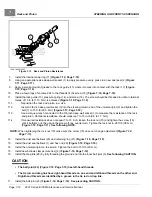
WHEELS AND TIRES
TIRES
See General Warnings on page 1-1.
TIRE REMOVAL
NOTE:
Tire must be removed or installed from the valve stem side of the rim.
1.
Remove the tire and wheel assembly from the vehicle as instructed above.
See Wheel Removal on page 8-1.
2.
Remove the valve cap and valve core and allow air to escape from the tire.
3.
If possible, use a tire machine to remove the tire from the rim.
3.1.
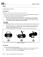
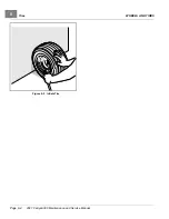
If a tire machine is not available, loosen both tire beads by applying pressure to the tire side walls and
pushing the tire bead away from the rim flange and into the rim well
(Figure 8-1, Page 8-2, Detail A)
.
3.2.
With the valve stem side of the wheel up, use a tire tool to carefully start the upper bead over the edge of
the rim
(Figure 8-1, Page 8-2, Detail B)
.
See following CAUTION.
CAUTION
• To avoid damage to the tire, do not use excessive force when starting the bead over the edge of the rim.
3.3.
When top bead is free of the rim, pull the bead from the bottom side of the rim up into the upper part of
the rim well. Insert the tire tool under the lower bead as shown
(Figure 8-1, Page 8-2, Detail C)
and
carefully pry the lower bead over the rim flange.
3.4.
Once the lower bead is started over the rim flange, the tire can be removed from the rim by hand.
A
1
2
3
5
B
4
6
C
1. Upper Tire Beads 2. Lower Tire Beads 3. Rim Flange 4. Tire Beads Positioned In Rim Well 5. Valve Stem Side Up 6. Tire Tool
Figure 8-1
Tire Removal
TIRE REPAIR
1.
Determine the location and cause of the air leak.
1.1.
Remove the wheel.
See Wheel Removal on page 8-1.
Inflate the tire to no more than 20 psig (138 kPa).
1.2.
Immerse the tire in water and then mark the point where bubbles are formed by escaping air.
1.3.
Determine the cause of the air leak.
See following NOTE.
Page 8-2
2021 Carryall 300 Maintenance and Service Manual
Summary of Contents for Carryall 300 2021
Page 2: ......
Page 16: ......
Page 551: ...80 2018 by Kohler Co All rights reserved KohlerEngines com 17 690 15 Rev...
Page 565: ...GASOLINE ENGINE HARNESS Wiring Diagrams Gasoline Engine Harness 26...
Page 566: ...Page intentionally left blank...
Page 567: ...GASOLINE KEY START MAIN HARNESS Wiring Diagrams Gasoline Key Start Main Harness 26...
Page 568: ...Page intentionally left blank...
Page 569: ...GASOLINE PEDAL START MAIN HARNESS Wiring Diagrams Gasoline Pedal Start Main Harness 26...
Page 570: ...Page intentionally left blank...
Page 571: ...GASOLINE INSTRUMENT PANEL HARNESS Wiring Diagrams Gasoline Instrument Panel Harness 26...
Page 572: ...Page intentionally left blank...
Page 573: ...GASOLINE FNR HARNESS Wiring Diagrams Gasoline FNR Harness 26...
Page 574: ...Page intentionally left blank...
Page 575: ...ELECTRIC MAIN HARNESS Wiring Diagrams Electric Main Harness 26...
Page 576: ...Page intentionally left blank...
Page 577: ...ELECTRIC INSTRUMENT PANEL HARNESS Wiring Diagrams Electric Instrument Panel Harness 26...
Page 578: ...Page intentionally left blank...
Page 579: ...ELECTRIC ACCESSORIES HARNESS Wiring Diagrams Electric Accessories Harness 26...
Page 580: ...Page intentionally left blank...
Page 588: ...NOTES...
Page 589: ...NOTES...
Page 590: ...NOTES...
Page 591: ...NOTES...
Page 592: ...NOTES...
Page 593: ...NOTES...
Page 594: ...NOTES...
Page 595: ......
Page 596: ......


