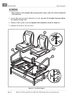

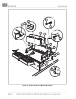


ACCELERATOR AND BRAKE PEDAL ASSEMBLIES
Brake Pedal Adjustment
Page 5-4
2006-2010 Turf/Carryall 272/472 and XRT 1200/1200 SE Maintenance and Service Manual
5
Brake Pedal Adjustment, Continued:
6. Adjust the brake stop bumper (22) up to increase
t
he distance between the pedal and the floorboard. or
down to increase
. Proper brake pedal height is 6-5/8 inches ± 1/4 inch (16.8 cm
± 6 mm)
7. Tighten the jam nut (31) to 8 ft-lb (9.5 N·m)
.
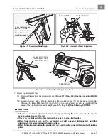
8. Adjust the clevis (16) by rotating it so that the clevis pin (8) can be placed through the clevis (16) and the
bottom hole in the bell crank assembly (11)
See following NOTE.
NOTE:
The spring (17) should not be under tension while the brake pedal is at rest.
9. Install the bow tie locking pin (21).
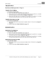
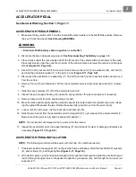
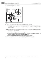
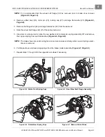
10. There should be at least 1/8 inch (3.2 mm) of free play (at the push rod) before the push rod begins to
press the master cylinder piston
See following NOTE.
NOTE:
Brake pedal free play is the distance the push rod (12) travels before the master cylinder piston
(18) is pressed
Also see
.
11. Perform all brake system inspections to ensure that the hydraulic brake system and the park brake sys-
tem are adjusted and operating correctly before placing the vehicle into service.
Inspection, Section 6, Page 6-1.
Figure 5-6 Push Rod Free Play
APPROX. 1/8-IN.
(3.2 mm)
FREE PLAY
Summary of Contents for CARRYALL 272
Page 2: ......
Page 14: ......
Page 18: ...1...
Page 52: ...5...
Page 90: ...6...
Page 110: ...7...
Page 112: ...8...
Page 128: ...10...
Page 170: ...11...
Page 224: ...13...
Page 284: ...16...
Page 302: ...17...
Page 308: ......
Page 309: ...Club Car R NOTES...
Page 310: ...Club Car R NOTES...
Page 311: ......


